Sunday, March 6, 2022

Geo whitelist, and Tor exit node blocklist (ipsets)

I wrote these two scripts to use ipsets and iptables to block Tor exit nodes, and to whitelist countries (e.g. drop all traffic from those not in the ipset).

They will load the last saved ipset file if the iptables rule is not loaded (assumes system was rebooted) which is fast. They will handle download errors and reload the last saved ipset file. Once loaded and when the scripts are run again they will update the ipsets and save the ipset files. The US has a fairly large number of netblocks, and it can take a little bit of time to create the ipset. I could not find any other examples that had this level of "self sufficiency" so I wrote my own.

https://github.com/lonney9/ipsets

Times are a changing, and I dont see the need to have my Oracle Cloud instance or IRLP node accepting connections from anyone anywhere.

Monday, January 24, 2022

Gain Master Antenna Model

A center fed 5/8 wave vertical covering 26 to 28 MHz, matched using coax for a capacitor and a stub, DC grounded, mechanically and electrically simple, no ground plane needed.

I ran across this interesting antenna design on VK5ST QRZ bio after completing a 10m FT8 contact yesterday.

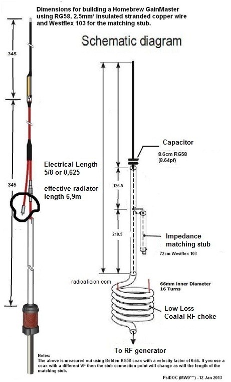
Gain Master antenna diagram

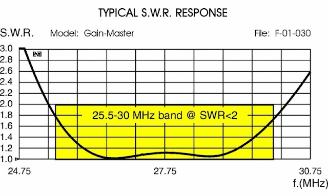
Gain Master SWR plot

Ok, that got me interested, center fed verticals don't get much attention. A while ago I discovered on my own they are pretty good, much better elevation pattern stability compared to end fed over a ground plane, quieter on receive and they perform quite well in my opinion :-)

As with all antenna designs, it's always good to model them to see what we can learn, and what to expect before getting too excited..


EZNEC Gain Master elevation plot

EZNEC Gain Master SWR plot


When modeled 15ft above average ground it has a shade more gain at 2.6 dBi, maybe half a dB more quickly looking at a conventional 5/8 ground plane model I have.

The SWR response is quite broad, 2 MHz bandwidth at 1.5:1 or better. This would flatten out even more with feed line losses etc. This antenna could easily cover the New Zealand 26 MHz CB band, 27 MHz CB band, and the bottom of 10 meters!

Model: Gain-Master

I had to change the capacitor value to 14 pF which resonated the antenna at 27.3 MHz and provided a very near perfect 50 ohm match leaving the stub length and position as is.

Transmission line 1 is the length between where stub attaches and the capacitor.
Transmission line 2 is the shorted stub length.
V1 where they meet is the 50 ohm feed-point (source).

----------

How does this antenna work?

Specifically the function of the capacitor and stub to match it.

The good thing about antenna modeling, is we can take antennas apart and put them back together again to learn how they work by making a change and looking at the result.

At the center of a split 5/8 wavelength dipole in EZNEC we see 180 + J 420 ohms:
  • Top half is wire extending beyond capacitor, bottom half is the outside of the coax shield down to the choke.
  • Capacitor in series with the center conductor tunes out the inductive reactance leaving 180 ohms resistive.
  • 50 ohm point is found where the stub attaches, the coax from this point running down to the choke is matched to 50 ohms.
  • The length of coax between the end of the stub (hanging off the side) and the capacitor forms the total stub length.
  • Assuming I got my math right: The length of the stub is a 1/4 wavelength at 25 MHz when the VF of 0.66 is taken into account! Why this length I'm not sure, we can shorten the stub to be a 1/4 wave at 27.2 MHz and with some trial and error find the 50 ohm point and a cap value that gives a 50 ohm match.

From there the antenna is simply a center fed vertical dipole made out of coax. The wire beyond the capacitor is the top half, the coax shield down to the choke is the bottom half, the stub hanging off the side would appear to have little to no effect.

An example of a 1/2 wave vertical dipole made of coax and wire is K9YC's Vertical Dipole, except being a 1/2 wave it doesn't need a matching network as its resonant on its own and close enough to 50 ohms. A simple series matching section could make it perfect. It wont have the same broad bandwidth however. Uses ferrite for the choke which is a much better choice especially for high power use.

As for the choke, its size and number of turns isn't close to anything on the chart at http://www.karinya.net/g3txq/chokes/. An analysis would need to be done on the Gain Master choke to better understand it. Since it remains an unknown I would personally use a ferrite choke such as those used by K9YC's vertical dipole as an example. For more about air core chokes see Air Core Coax Chokes: Good, Bad and Ugly by VE3VN.

Getting back to the stub for a moment, using a shorted 1/4 stub I've seen used as a technique to broadband inverted L antennas on 160m - http://mobileers.com/main/wp-content/uploads/2017/01/N9LYE-22L22.pdf (web.archive.org - original is gone). Experimenting with the model as a 5/8 split dipole (source in the center) and the capacitor to get 180 ohms resistive, adding a 1/4 wave stub by it self does have a broad-banding effect, but that is likely a bonus secondary function of the matching stub in the Gain Master design.

----------

I ran the model through AutoEZ to use variables and the optimizer, it made very incremental changes to the values for the capacitor, the stub length and position - basically nothing to be gained, this design is perhaps already quite optimized!

Adding a 1 to 5 meg ohm 5W metal film resistor across the cap to bleed off static buildup also a good idea.

Sunday, January 16, 2022

10m Surprise

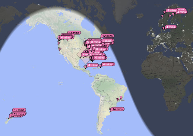
Two days ago a CME occurred, I happened to be on 10m FT8 as prior to this the MUF map suggested the band might open.

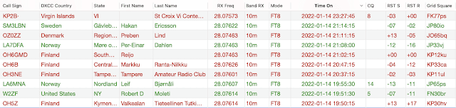
Ten minutes before mid-day my eyes just about fell out of my head when I saw northern EU stations calling CQ up-to 17 dB SNR! A quick look at SolarHam confirmed there had been an CME event, and that I had indeed caught the effects of it as it happened.

Over the next couple of hours logged Finland (4 stations), Norway, Denmark and Sweden. Nothing below or beyond that area showed any signals here.

The polar path was having the usual effects on signals, from "fuzzing" them on the waterfall, to one or two decodes and then nothing, quite a number of partially completed contacts in the FT8 sequence. The signals from northern Europe would come in waves, they'd be there for a couple of minutes then gone again, a few minutes later they're back for a few.

ZL even appeared for a little bit, but nothing else across the Pacific.

EU on 10m, that's a first for me.

10m PSK reporter

10m QSOs

Yesterday 10m served up another surprise, while I didn't get any openings to new DX, some very short hop propagation appeared, and I logged three WY stations consecutively, and finally got NM on 10m which completed the last two states I needed for WAS on 10m. That makes ID on 15m the last one needed to complete 5-band WAS.

Wednesday, December 1, 2021

FT8 - Now it makes sense!

Dark side cookies

For a time FT8 seemed pointless to simply log the minimum for a contact in an automated way and move on, the social side and having a chat getting to know someone, and share ideas is removed from the equation.

I always did see FT8's good points and purpose, its a weak signal mode, efficient, and gets the job done neat and tidy. 

Ideal for contesting, special events, or working a DX-Pedition for example to get that rare one in the log where all that is happening is exchanging of callsigns and signal reports anyway. FT8 simply took that function, and made it efficient. No problem with that.

But I was being a Curmudgeon, so back in April this year I tried out FT8 to at least figure out how to drive it. With a busy summer out of the way and fall around the corner I decided time to get a little more serious and start using logging software and maybe work towards getting awards, and QSL cards to stick on the wall.

The result was MacLoggerDX, WSJT-X, JS8Call, Fldigi and Flrig Integration. MacLoggerDX does the right things, and once configured makes rig control, and logging contacts with WSJT-X, JS8Call, and Fldigi seamless, couple mouse clicks and its all done. Now there is no excuse, the tools are in-front me to get to work.

Now it makes sense, a lot of sense. Most FT8 ops upload logs to LoTW, which is appreciated if like me you want them to also count towards awards for example. After a few weeks I had logged and confirmed contacts all over the world, and sent and received a number of QSL cards.

This reminded me how much I enjoyed sending and receiving paper QSL cards too. Today when everything is electronic and instant, it's nice to receive a physical object from somewhere that took a journey.

This mode also spurred me to upgrade my antenna systems. The OCFD was replaced with 130 ft doublet fed with 600 ohm line into a remote auto tuner which is interfaced to the rigs ATU port. This makes band changes seamless, and enables me to operate on all bands 160-10m. I finally assembled the 6m 3 element LFA Yagi I had bought, which then blew down in strong winds a few weeks later, and since tediously unbent with a vice, straight edge and a mallet. See Thats the end of Six meters for a while..

Maybe the spark gap ops didn't like the new kids running vacuum tubes at the time either. It's just an evolution of technology that enables us to set the bar higher. DXCC is easier, so we get that then set the next goal and keep going, and/or set goals with friends and compete.

For example, KL2R and I set the goal of a clean sweep, logging and confirming a contact on every band. This turned out to be quite fun.

I've also logged contacts with friends I've since not heard from in a long time, and follow ups via email sometimes result which is a nice surprise.

All the same I enjoy text chats on JS8, PSK31, and talking to people on voice modes just like always. Remember to stop and smell the roses.

I've simply added an additional mode I can use for awards and other goals, and to get some of those nice QSL cards that would otherwise be much harder or if not impossible to get.

100 countries confirmed in LoTW under three months - I started on September 10th, and 100th country was confirmed on December 1 by E75C. Simply from putting in a consistent effort with a modest station - a single wire antenna, 80W, sometimes 350W when needed.

Time for a break from chasing DX, work on some other projects and think about the next goal..


8J1RL QSL card

Sunday, November 14, 2021

Doublet Antenna

130 ft Doublet Antenna, covers all nine HF bands 80m - 10m, and optionally 160m with reasonable patterns.

600 ohm feeder > 1:1 ATU balun > switching network > Remote antenna coupler / tuner. 

Doublet antenna remote ATU

The conundrum I had was how to get all nine HF bands 80m - 10m, and 160m from one antenna, with reasonable patterns, performance, and rated for high power. My limitation is having 1/4 acre where I can fit at most 130 ft of wire in a straight line horizontally.

Decided a doublet fed with 600 ohm open line into a remote ATU was the best option. Also, linking the feeders together and driving it against ground as a T antenna enables use on 160m, and a useful set of alternate patterns on 80 through 40m.

The matching network we bring into the 21st century, high quality remote ATU and high quality 1:1 ATU current balun. Remember, any system is only as strong as the weakest link..

  • Balun Designs model 1171 5 kW 1:1 ATU current balun (studs in, studs out).
  • Remote ATU Stockcorner JC-4s 1 kW automatic antenna tuner (5 stars on eHam).
  • Doublet and feeder from TrueLadderLine. Could built it, cheaper to buy it vs time.

The JC-4s ATU can be interfaced to Kenwood and Icom rigs to operate via the Tuner button, and setup to bypass keying an amplifier during tuning. See JC-4s Automatic ATU and Icom IC-7300 Hints on PA0FRI's site.

Initially tuner was very slow to find matches on the upper HF bands when interfaced to the Icom ATU port, but was very quick using the supplied manual tuner interface and 15W carrier to tune. The TUNE carrier power in my Icom 7300 was under 10W, raised it to around 15W the per the service manual which solved the problem.


T Antenna mode, this turns it into a vertical with top loading by feeding the two legs of the feeder together against ground:

  • 160m - 1/8th wave vertical, top loading results in uniform current along the vertical.
  • 80m - 1/4 wave vertical, top loading moves current max to top away from ground noise.
  • 60 to 40m - not sure how you would describe it.
Since the ATU is 10 ft above ground, this places it around 15% up the total vertical length, EZNEC predicts reasonable impedances.

For a while I've been undecided if the T (or an inverted L / vertical monopole) should be directly connected to the ATU's "hot" output terminal, and the ATU ground connected to ground, OR if the 1:1 balun should be left in place, with the T connected to one terminal and ground to the other.

According to W8JI's Counterpoise Systems page the latter should be used, as the overall antenna system is neither perfectly balanced or un-balanced. It is better to force equal and opposite currents, and ensure the coax and control cable shields are choked/isolated so they do not become part of the antenna system. The shields should still be grounded beyond the choke for lightning protection per NEC.

Feeding the system with the balun inline resulted in better matches on 40m, and got rid of an RFI problem.

Sept 2023 I have a remote switching network in the works that will be driven from the JC-4s A/B signal allowing me to remotely change between a doublet and vertical T. More about that once I get it installed.

So, how does it work? I had it up on Oct 21 but connected to my Icom AH-4 tuner which limited me to 100W while I waited for the JC-4s. With the 100 ft feeder strung up to the AH-4 in a temporary location it tuned all bands except 160m.

The first thing I noticed was how much quieter it is on receive compared to my OCFD which had a Balun Designs OCF balun optimized for the job with a good amount of current choking. Now I wonder how much noise is picked up by the coax shield and leaks or couples past the balun to the antenna, then back into the receiver? Noise dropped two to three S units between 80 and 20m.

So far the results on 12, 15, 17, 20, 30m have been good on FT8. SNR each way mostly equal, and looking the TX/RX performance with other stations in my grid on pskreporter things are fairly comparable.

Morning of 22 Oct 21 I worked 8J1RL Antartica on 40m FT8, about 1 hour after sunrise.
Confirmed in LoTW so not making this up :-)


8J1RL FT8 QSO


Later, 7P8RU Lesotho on 17m FT8 (since got them on 12, 30, and 60m), and if that wasn't enough.. After days and days of trying to get 3DA0WW Eswatini using the OCFD and up-to 500W on different bands, I successfully worked them at greyline that evening on 80m FT8 with 80W

That I managed to get those three rare ones with only 80W TX on my end was a nice surprise.

Weekend Oct 30 was CQ WW SSB contest, we had some good propagation on the upper bands. Saturday I worked a number of stations on 10m SSB with 100W in South America, Caribbean, and Japan late in the evening. KL7RA a well known contest station in Alaska commented I had the biggest signal on 15m they'd seen.. Probably something to do with one of those 9.8 dBi lobes that falls north west :-)  also worked them on 20 and 40m. 9/10 times I'd get heard on the first or second call, following morning on 20m got OH8X (super station in Finland), and a couple others.

Also got excellent reports on 75m AM running "bare foot" 25W carrier power.

13 Nov 2021, I now have the JC-4s installed, and feeder length tuned for good matches on all bands, I used my RigExpert to do this so I can be sure that complex impedances the tuner sees are reasonable.

14 Nov 2021, I see Kuwait operating on 20m FT8, watched for a while no decodes. Checked again an hour or so later, decoding up to -6 dB, tried for 10 - 15 minutes with 80W, no luck. Hit it with 400W and completed the contact. I had to pick my self up off the floor when the RR73 appeared. From my location near Seattle, Kuwait is right over the north pole, middle of day here, night there. Unbelievable.

I'm suspiciously optimistic this antenna just seems to work better than all previous wire antennas I have used by a good margin (dipoles, trapped dipoles, OCFD), it keeps surprising me.

Actual readings taken with a RigExpert analyzer connected to the 1:1 ATU balun in doublet mode:

Band

R Ω

X Ω

SWR

10m

162.2

-93.9

4.4

12m

136.3

-114.1

4.8

15m

56.7

-178.6

13

17m

35.7

-163.1

17

20m

52.7

-259.6

28

30m

486.0

151.9

11

40m

102.4

-442.2

41

60m

98.1

109.8

4.7

75m

137.9

-445.6

32

80m

313.5

-659.6

34

160m

12.0

-141.9

38

This is with the antenna at a height of about 55 ft or 17 m, and approx 70 ft or 21 m of 600 ohm open wire line.

This shows me that the ATU has quite reasonable complex impedances to match, or no wild extremes at least.

R is a little low on 160m but at 130 ft or 40 m long the doublet is well too short at 1/4 wave length, but it does work no doubt with reduced efficiency. In T mode on 160m it would work much better as a DX antenna on transmit at least..

This also highlights the trap of assuming a 4:1 balun should be used, in nearly all cases this would lower the impedance too much. See Tuner Balun 4:1 or 1:1 for more about that.


Introducing the "All Band" Doublet - Cebik.

10 Frequency Asked Questions about the All-Band Doublet - Cebik.

Tuner Balun: 4:1 or 1:1? - G3TXQ.

80-Meter Doublet - KV5R.