The STREB VHF Compact Beam by Bert Looser ZL4IV is a 2m antenna which appeared in October 1992 BREAK-IN, the official amateur radio journal published by NZART (New Zealand Association of Radio Transmitters).
A local ham and good friend Bill ZL1DEF (SK) gave me the temporary one he built to play around with sometime in 1994. The day I tried it out must have had some enhanced propagation as I could access a 2m repeater that was usually just out of reach with out help from a band lift. I thought wow, this antenna has the secret sauce I need!
I took it down and planned to build a weather proof version. That never happened and another friend of mine at the time commented probably a band lift, which I would later confirm since an 8 element NBS Yagi and 100W couldn't access or hear that repeater under normal conditions.
But this unique antenna never quite left my mind, getting back into ham radio around 2007 after a 10 year break the topic of this antenna came up while chatting on a local repeater and I was able to obtain copies of the two pages above.
Another 14 years later and having learned to model antennas over the last couple of years I decided it was time to model the STREB and take a closer look.
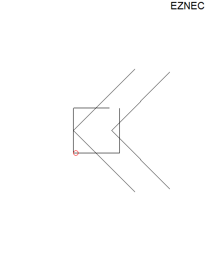
I created a model per the dimensions and tube thickness used in the article (6.4 mm or 1/4 inch) in EZNEC, the front to back ratio was low at around 10 dB, and resonance was well below the 2m band. Not sure why the discrepancy.
I contemplated trying to optimize it by hand, I've done this in the past with other antenna designs but the motivation didn't appear, so I decided to gain some experience with the the AutoEZ optimizer and put it to to work..
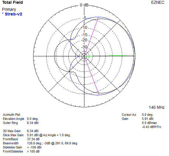
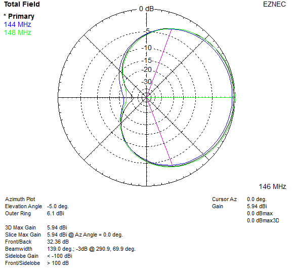
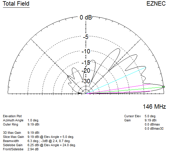
Well, blow my socks off! AutoEZ optimizer vastly improved the front to back, 20 dB or better across the 2m band, and moved the resonance to 146 MHz. The feed-point impedance came out around 135 ohms, using a section of 75 ohm coax to transform the impedance and wound on a toroid to also form a choke would bring that to 50 ohms with the SWR rising past 1.5:1 at the band edges according to EZNEC.
One change I made was aligning the two parasitic elements in the same plane in both models with a 50 mm spacing, the article has them either side of the RF cage (more or less a 1/2 wave dipole bent into a square fed at one corner), this didn't seem to do anything useful other than offset the pattern from the plane of the antenna.
See 2m-STREB for model files etc.
Article figure 5 measurements after AutoEZ optimization:
B = 1013 mm (Reflector/rear element)
C = 62 mm (Gap between open ends of RF cage)
D = 270 mm (Height) x 209 mm (Length) (RF cage top half)
E = 271 mm (Length) x 270 mm (Height) (RF cage bottom half)
You might think, that's a mildly complicated antenna in an effort to reduce the size (but still poke your eye out with), and doesn't have a direct 50 ohm feed. What else is there? A Moxon rectangle has a similar size reduction, is simpler to build, direct 50 ohm feed, and are a well known tried and true design at this time. Interestingly both the STREB and Moxon appeared at about the same time.


