Wednesday, December 25, 2019

Audio-technica BPHS-1 and Icom

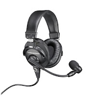
I received a Audio-technica BPHS-1 headset for Christmas from my wife :-) The BPHS-1 looks to be a quality headset that is well rated on Amazon, Audio-technica's site and other places.

K8JHR wrote an article called Headsets I have tried, like or recommend which includes the BPHS-1.

I quickly discovered that Icom rigs (and Elecraft) are setup for electret condenser microphones, where as the rest use dynamic microphones. Electret mics are powered, dynamic mics are not and are about 20 dB lower in level. The BPHS-1 uses a dynamic mic.

Will a dynamic mic work with an Icom? Maybe..


Next, cables. The BPHS-1 comes with a cable that has a 1/4" plug for the headphones and a 3-pin XLRM-type connector for the mic.

  • First, the mic pin in an Icom supplies 8 VDC for the electret mics they use, when used with a dynamic mic we need to use a DC blocking capacitor otherwise the magic smoke will come out. Heil recommends a 1 uF tantalum (noted in heilsound.com link above), some posts on QRZ suggest anything up-to 10 uF is good. I found some 2.2 uF 16V tantalum capacitors on Amazon, these are polarized so the positive leg should connect to the mic pin in the Icom.
  • Mic side: Need a female 3-pin XLRM, I chose this cable from Amazon, can cut to length and wire into a 8-pin Foster mic plug with the DC blocking cap for the Icom's mic socket.
  • Headphone side: 1/4" to 3.5mm adapters are easy to find, thou I prefer a short cable here so the 3.5mm jack in the rig doesn't have an adapter and 1/4" plug hanging out of it. A quick search around Amazon finds MillSO 1/4 to 3.5mm Headphone Adapter, TRS 6.35mm Female to 3.5mm Male 1ft cable.
  • A cheaper option is to just cut the 1/4" and 3-pin XRLM plugs off, put a 3.5mm plug on the headphone side, and 8-pin Foster mic plug on the other plus the DC blocking cap.

Parts ordered, plan to have it together next week..

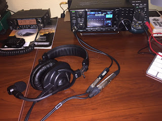
Parts arrived yesterday 29 Dec, I installed the DC blocking cap into the mic plug, I found I could fit it in-between the unused pins:
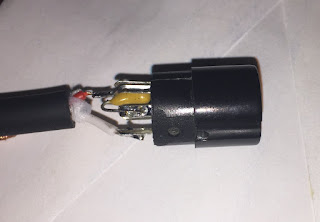


I cut the XLRM cable so it matched the 1/4" to 3.5 mm adapter cable length, and it looks like this:


Wiring diagram: Headset diagram from BPHS-1 manual (left), the mic connector diagram is from my Icom IC-7300 manual (right), with the connections shown as I wired it:


The shield (shown in green) I folded back in the mic plug and "clamped" in with the strain relief so it's grounded to the frame of the radio via the plug.

After adjusting the mic gain and compressor settings on SSB, I found mic gain at 80% and compressor at 5 would drive the IC-7300 about the same as the supplied hand mic with mic gain at 40% and compressor off. I did this by doing several comparisons watching the RF power output and listening to my self via the rigs monitor function with the headset on.

I have yet to do an on air test on SSB. I was able to do a quick test on a 6 m FM repeater, on FM the speech compressor option is unavailable and with the mic gain set to 100% the deviation is too low.
Sunday, December 22, 2019

AL-80B Keying Interface

KV5R wrote a nice article (Amp Interface) on building a solid state keying / relay interface for use with Icom rigs, using an SPST-NO MOSFET switch. I also have an Icom rig and an Ameritron AL-80B.

The nice thing about this is it's super simple, much faster than a mechanical relay and is opto-isolated.

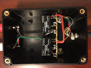
I had ordered some parts for another project a while back, part of which was to rebuild the keying interface so I could key two devices. That project got shelved, but today I decided to rebuild the interface as originally planned since I had the stuff to do it.

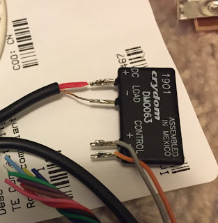
Version 1 (with the heat shrink removed):


I had this hanging out the back of the rig, that was ok.

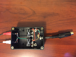
Version 2:


Only the orange and grey wires are used from the Icoms pigtail, the rest are just tucked out of the way.

The solid state switch's control voltage is 3 to 10V, but work ok from 12V. With two of them I wired them series for use with the rigs accessory jack which supplies 12V when keyed. With this I can independently key two separate devices with a closing current of 3A at up-to 60V each.

Parts I used:
  • Project box is a "Zulkit Waterproof Plastic Project Box ABS IP65 Electronic Junction box Enclosure Black 3.94 x 2.68 x 1.97 inch (100X68X50mm) (Pack of 2)", from Amazon. I have found it quite difficult to find good project boxes.
  • DIN plug and pigtail came with my IC-7300, I simply cable tied once for strain relief and a second time looping it through two small holes I drilled to stop the cable from rotating. This secured it nicely since I didn't have anything better on hand.
  • Solid state relay is a Crydom DMO063, Mouser part # 558-DMO063. Can also be found on Amazon, and other places.
  • Barrier Terminal Blocks TERMINAL STRIP 6 LUG, Mouser part # 158-1006.
  • RCA Phono Jack, Mouser part # 490-RCJ-032.

Monday, December 16, 2019

Ameritron AL-80B AM Operation


Since I get into a bit of AM on 75 m, I had wondered about using my AL-80B for some extra Amplitude Modulation power :-)

While chatting on 75 m AM today I raised the question about using an AL-80B on AM. A couple of the ops in the round table we had going said they work great, in-fact one who later joined-in was using an AL-80B!

Setting up an AL-80B for AM use is pretty simple, the goal is 100W unmodulated carrier power on AM from the amp.
  • With the Icom IC-7300 set to 30% / 30W on RTTY mode, tuned the amp, this delivered about 400W output.
  • Switching to AM I reduced the drive power (to 20% in my case) to where I got 100W unmodulated carrier power from the amp, modulated voice peaks are around 300W PEP.

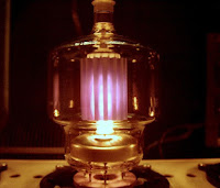
With this configuration I found that anode would start to show a dull cherry red color after a few minutes of transmitting which is perfect for the 3-500Z tube.

Signal reports from the group indicated going to 100W carrier power made a worth while improvement over the 25W carrier / 100W PEP from the IC-7300 on AM.

The AM operators in the Pacific North West are a friendly bunch, if you enjoy informal round table QSOs that can last a while, then this is the place (3.870, 3.877 and 3.885 MHz).

Wednesday, November 27, 2019

New Desk version 2

Earlier this year I got some IKEA for the shack, the setup was ok for ham radio use where I might spend an hour or two.

The company I work for offers the luxury of working from home up-to a couple days a week (perk of working in tech) which I've been doing more of recently. I was finding the ergonomics of my IKEA setup not great after 7 or 8 hours of use.

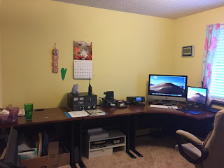
I needed something better. After some searching I came across Cymax Bush Business Furniture, yes it costs a bit more but the quality is good with a 10 year warranty. I got the Bush Business A-Series Left Corner Office Suite in Hansen Cherry, which is just two Series A 36W Desks and a Series A 48W Corner Desk.


Much better!

The Bush Business setup was just over $600 delivered, not cheap but the quality is there. Feels solid and can handle up-to 200 lb / 100 kg, ideal for those heavy vacuum tube amps. They shipped fast too, ordered Saturday delivered Wednesday morning, had it assembled and in-place by the end of the day.

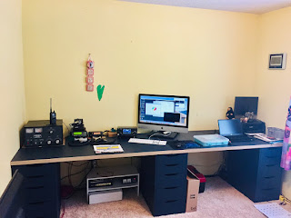
Previous setup:


The three IKEA draw sets are now under the window just out of view on the right in the first pic, these made up most of the cost of the previous setup, the two IKEA table tops were $30 each at the time I got them so no big deal.

Saturday, November 16, 2019

A Better Off Center Fed Dipole?

20m 3D Far Field Plot - GAL-ANAI've always liked the OCFD, they're a simple multi band antenna for HF. One balun and some wire, and easy to tune gets you 5 or 6 bands.

However conventional OCFDs present a set of trade offs. 80m and 40m resonance is low, and 20m and 10m resonance is high placing the low SWR points at the band edges. This is due to the harmonic relationship of the bands and the detuning effect the proximity of the ground has at lower frequencies, lowering the resonant frequency.

One can't quite get away from needing an antenna tuner of some description. We can make do with the internal "touch up" tuners in most rigs. I want something that's nicely matched so I don't have to fuss with tuners, or load the AL-80B into a high SWR. Tuner or not high SWR is still present at the balun which can stress the core heating it up, heat is lost power.

One of the more well known solutions is ON4AA's "CL-OCFD" design which moves the resonance on 80m (and optionally adds 30m too). This one locates a capacitor at the electrical center of the antenna, which only affects 80m resonance moving it up into the band.

K5GP's "A broadband 80/160 meter dipole" is another example of using a center loading network.

A July 2020 article in CQ magazine Multiband Off-Center-Fed Dipoles for 160 and 80 Meters uses a 20% offset (improves 15m band coverage), two capacitors in the 160m version, the 80m version uses one in the center same as CL-OCFD.

Focusing on 80m, the CL-OCFD fixes 80m but doesn't solve the rest, 40m is still low and 20m and up are still high.

I have modeled two possible solutions - model files here.

The first solution I call FPL (Feed Point Loading), making the antenna longer to bring 10m and 20m down, and adding 175 pF series capacitance at the feed-point (e.g. insert it between the long leg and the balun terminal) to pull up the lower bands by tuning out the inductive reactance.

The cap has a greater effect lower in frequency where it's needed more, and a diminished effect on the upper bands. This moves the resonances into the phone segments of 80, 40, 20, 10m, and 12m as a bonus. Unfortunately 17m and 6m resonance is still low in the model, can't win 'em all!

Per the model:
  • 41.7m wire.
  • 33% offset.
  • 175pF cap at balun / feed point.
  • 16m / 55 ft height above ground.
  • 13 AWG, 0.5 mm PE insulated wire (The Wireman 531 material).
  • 150 ohm feedpoint, ok with 4:1 current balun.

Advantages of this approach 150 ohm feedpoint, even on the lower bands. This is achieved because the antenna being longer raises the impedance. Close enough for a 4:1 balun.

After a lot of searching, I managed to turn up a few references where a capacitor is placed at the balun:

The second solution uses a compensation coil.  I got the idea for this compensation coil from WA7ARK's End Fed Multi Band Antenna slides. By optimizing the antenna for 40m this shifts the upper bands further up and out of band. These can be corrected with a 1.7uH compensation coil placed in the end of the long leg, 6% in of the overall length. Getting this positioned right may result in some trial and error with out a good antenna analyzer. 80m resonance can optionally be moved by using ON4AA's OCFD-CL method of placing a capacitor in the electrical center.

Per the model:
  • 40.7m wire.
  • 34% offset.
  • 300pF cap in the center (optional to move 80m resonance).
  • 1.7uH compensation coil located in the end of long leg, 6% in overall total antenna length.
  • 13 AWG, 0.5 mm PE insulated wire (The Wireman 531 material).
  • 135 ohm feedpoint, use 2.5:1 current balun.

That's what the models say at least :-)

Balun Designs sell both 4:1 and 2.5:1 baluns designed for OCF antennas. I've bought several of their baluns over the years and they are very well made. However they can lack choking performance below 40m, adding a second CM choke below the balun is recommended.

The capacitor needs to be RF transmitting types or capable of handing the RF current passing through them. The cap should have a 1 to 5 Meg ohm 5 watt metal film resistor across it to protect it from static buildup.


Nov 2020, I finally got a compensation coil installed with mixed results which merits further experimentation..
  • 10m came down around 500kHz to 28.8, so still 400kHz too high. I tried less turns, more turns, moved it between 6 and 8ft from the end, couldn't get it to come down further.
  • 12m resonance below the band.
  • 17m resonance below the band.
  • 20m moved down about right, but SWR 1.5:1 across the band.
  • 40m is about right.
  • 80m resonance for some reason at my location has always been further up the band than expected and from previous experience with OCFDs.
I'm using my existing 4:1 current balun with this.

Oct 2021, Noticed SWR rising when running the amp on 40m (tuner off/bypassed). While troubleshooting I removed the LDG -RT-600 remote tuner I had inline about 60ft from feed-point. Put the analyzer on the antenna again, and found the resonances and low SWR points on 40, 20 and 10m had moved a lot! Long story short the RT-600 must have an impedance bump inside it? Which was why I didn't get the expected results from the compensation coil. Now it should be fairly easy to get the coil to do the trick.

However I decided I want agility across all ten bands from 160 - 10m, and be able to run the amp when needed. After research, the solution I have settled on is a 130 ft doublet fed with 600 ohm open line into a new 1 kW remote ATU via 1:1 balun. More about that at Doublet / T Antenna.

The OCFD has been retired, we had a good run, it is a nice simple antenna where the most expensive part is a good 4:1 current balun, the rest is wire and coax, gets you on several bands easily.


An analysis of the original Windom - Notes of Mr. Windom's "Ethereal Adornments" (by L.B. Cebik, W4RNL). An interesting read since what we might call modern coax fed OCFD and the more recent EFHW designs using 49:1 transformers evolved from the Windom.

I also found the original Windom QST article from September 1929 in the ARRL QST archives online, another interesting read.


Models are good starting point, and a way to investigate and better understand antenna systems. These tools can also help guide us to and validate the final result, if a good correlation is observed in the real world then we can have confidence the patterns and other information are accurate.

The models I have created and made available may contain errors, or overlook something someone more experienced can see.

Thursday, October 17, 2019

WSPR - Turning off MW Band Attenuation for 630m

About three weeks ago I decided to turn off the MW band attenuation (MF Band ATT) in the Icom IC-7300 - this is a sub menu option in the settings that is on by default (Menu > Set > Function > MF Band ATT), this adds 16 dB attenuation per the manual. Wow what a difference! I started spotting stations much further away from Australia, Hawaii, Alaska, midwest to the east coast.

I've been spotting these stations semi-individually on and off, finally got a good selection of them in one night:
  • VK4YB - Roger's 630m antenna is something else.
  • K9FD - on a former AM broadcast site with radials intact on an Island, dream location!
  • K3MF
  • K5DNL - holds the distance record for a QSO on 630m with VK4YB!
  • KL7L


The antenna I'm using on receive is the ZS6BKW with no additional matching, just an HF 1:1 current choke at the bottom of the ladder line, remote ATU (bypassed) then 10ft coax drop to ground where it runs around to the other side of the house. The other RX settings I configure when running WSPR with the IC-7300 are NB and NR off, notch filter off, AGC fast set to 0.3 seconds.

Since turning off the MW band attenuation, I would start spotting the closer stations in California as soon as it got dark through until sunrise like clockwork. First I thought it was propagation changing with the D layer absorption which quickly disappears at sunset and quickly returns at sunrise.

Turns out it's more than the D layer at work, there are several strong AM broadcast stations in my area, during the daytime they are very strong and overload the receiver in the IC-7300. At night these stations lower output power and/or change their antenna pattern, this reduces signal levels at my location to a level where the receiver can cope.


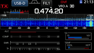
Screen capture of the strong signal on 850 kHz during daytime, S meter maxed out at +60dB. There are several more at +40 to +50dB.


630m band WSPR frequency during daytime, the S meter hovers around S9 +15dB. Band scope shows the "mess" these strong AM broadcast stations create in the receiver.


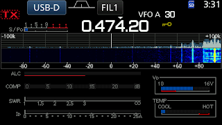
630m band WSPR frequency at night, the S meter hovers around S1 when AM broadcast stations reduce power and/or switch their antenna patterns.

Note: The time displayed on the IC-7300 clock top right is UTC.


Update 04 Dec 2019:

Since switching back to using an OCFD a few days ago, I no longer have the receiver overloading issue during the day on 630m. It seems to have knocked back the signal levels from the AM broadcast stations enough but with out appearing to adversely affect the WSPR receive performance.

Saturday, September 21, 2019

Gain vs Wave Angle

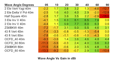
Something I've noticed is that most don't consider is the whole picture when it comes to antenna gain. Often only peak gain at the wave angle it occurs at is quoted. Sometimes a pattern is shown with no gain figures which is useless, this is often the case with verticals.

To build a picture of what one might expect when considering low band DX antennas, I feel it's better to consider the gain at different wave angles.

To illustrate this, I created a table in a spreadsheet with several different antennas and the gain they have at different angles. LiberOffice Calc has the option to fill cell background color based on the value. The table is sorted based on the gain at 5 degrees.


I used MMANA-GAL for the modeling of these antennas. Most are 40m antennas, those that can be matched on 80m are also shown.

Wire antenna heights are 40ft/12m, the inverted Vs are 15m/50ft, the delta loops have a minimum height of 1m/3ft.

Nov 15 2019:
Looking at the models of OCFDs again - I realized due to the lobe formation being either side of the X or Y axis on 40m and above, the far field plot does not show the peak gain as its simply sliced down the X axis. The geometry would need to be offset such that one of the main lobes aligns with the X axis. Comparing the elevation and gain results on the calculation tab with a plain 40m dipole vs an 80m OCFD on 40m band, the OCFD has around 1 dBi more gain at the same elevation angle (52 degrees when 12m above ground), which comes from the two broadside nulls that form. Under far field plots, the far field elevation angle can be changed, comparing gain at 40, 30, 20 and 10 degrees shows the OCFD having about 1 dBi more than a dipole at the same height.

I'll need to update my table..

Monday, September 9, 2019

ZS6BKW Antenna

What else is there that's under 100 ft, at a minimum covers 40 and 20m with out the need for an ATU, and will work on 75m?

After considering a few ideas, I took a closer look at the ZS6BKW antenna which is an optimized variant of the well known G5RV. This antenna checks the boxes on these points:
  • Light weight - no traps, coax etc hanging.
  • Low SWR on 40 and 20m, can run ~1kW with the AL-80B.
  • Respectable gain on 20m if you have the luck or luxury of orientating the broadside to favor somewhere of interest.
  • Will work on 75m with the remote ATU I already have. It's essentially a 1/3 wave dipole, as such has reduced efficiency since the resistive component falls rapidly when a dipole is under 3/8 wave length.
  • Also covers 17, 12, part 10 and 6m with low SWR.

Spent a couple weeks reading everything I could find, and playing with models - one is included with MMANA-GAL, others can be found online.

Decided it was worth trying out. Initially I was going to order the parts from The Wireman and build it my self, but found a source of these pre-made cheaper and better built for $60 (normally $90) plus shipping from Amateur Radio Supplies => ZS6BKW G5RV 80, so went that route. 

Current setup:
  • Antenna apex at 50ft, ends in inverted V configuration.
  • K9YC inspired choke balun - 7 turns of RG-8X through two mix 31 clamp on ferrites.
  • Remote ATU between the choke and coax to the shack. 

How does it work?
  • Except for 15m, low SWR on six bands from 40 to 12m, parts of 10 and 6m.
  • Remote ATU dials it in on 75, 60, and 15m, brings the total to nine bands.
  • 30m is the odd one out, ATU fails to find a match in my case.
  • Performance on 75m wasn't great on transmit, but it's better than nothing. My OCFD is notably better on 75m being a full 1/2 wave on this band. This may be why the G5RV is popular, at 10ft longer than the ZS6BKW that might make enough difference on 75m for it to be "good enough".

Nine bands where only three need an ATU, with 93 feet of wire in the air is OK by me. 30m might be an issue for some, but you can't always win 'em all :-) 

Links to further information:

Monday, August 12, 2019

Bay of Islands ARC Repeater Site

Following on from the Auckland VHF Group Repeater Site post, some more pics from the archives. This time of the Bay of Islands ARC Repeater Site, photos I took from around 2007 when I had the task of reinstalling the equipment after it had been removed for re-alignment.

This site was established with the help of the Auckland VHF Group in the mid 90s to get the national link extended north via a sister site between here and Auckland called Brynderwyn. NZART map here - its approximate at best. Google Map that I created here, the locations are with-in tens of feet in most cases.

Since these photos were taken when I was last there, the 2m repeater has had some changes with the addition of CTCSS for IRLP node 6398 link, there are more recent pics on their homepage and some from when the tower was erected.


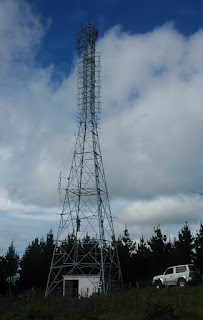
Pic of the tower and antennas. Like Klondyke, the 2m repeater antenna is constructed from angle iron, welded, and hot dip galvanized, but is a simple pair of 2 half waves in phase for around 10 dBi of gain, hard to see as they are end on in this pic. At the top is a 4 dipole stack for the the 70cm repeater. This configuration resulted in the 2m and 70cm repeater performance and coverage being closely matched in most cases. The link to Brynderwyn is a set of four 7 element Yagis with around 17 dBi? of gain, the Brynderwyn end has the same antenna configuration, this is needed because the 70 mile path is not ideal.


Inside the building.
Tait T300 gear.
146.750- also had a 50W PA in the back.
439.975- had the matching Tait 50W PA.


Thursday, July 4, 2019

New Desk

After using a folding table for the last few months, 'twas time for a something better.

I had considered The Great Ham Radio Desk Project, but after looking around IKEA I found something I liked better, more so since IKEA was having a sale at the time.

The spare room/office/shack is 120" wide across the back wall. What I ended up getting were three sets of draws and two table tops, the table tops are 59" x 29", the 29" width is nice, as it allows plenty of depth for radios, computers etc with space in-font.


The total was about $270 less tax and delivery fee, took an afternoon to put together.


Left to right, Ameritron AL-80B, Kenwood TH-D72A HT on top, Motorola MCS 2000 33cm/900MHz radio, Kenwood TM-731A, Icom IC-7300, 27" iMac (2014, 5K), under the iMac is a Windows 7 laptop which runs all the ham radio applications.

Plenty of room for more stuff! Plan to add some shelves to mount the Kenwood and Motorola mobile rigs, control boxes, and antenna switches etc.

22 Nov 2019:

This arrangement has been superseded with New Desk version 2.

Saturday, April 27, 2019

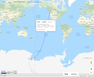
WSPR - 40m, ZL5A Scott Base Antarctica

WSPR pulls out another surprise.

Adam Campbell / ZL5A from Scott Base Antartica:


Tuesday, March 19, 2019

WSPR - 40m, 1 Watt, 16441 km

Distance wise, this is the 2nd best spot I've reported yet at 16441 km / 10216 mi, from ZS1LCD in Cape Town South Africa who was running 1 watt on 40m [7MHz]. ZS1OA remains king at 16511 km / 10259 mi on 30m [10MHz], and ZS3D is a regular in 3rd place at 16233 km / 10087 mi on 40m.


After running WSPR for about three months, I took a break from it about a week ago having built up a good feel for what I can expect with the current antenna configuration. Last night I had it running again after adding a 20 ft horizontal wire to the top of the 43 ft vertical turning it into a 1/4 wave inverted L on 80m.

With the exception of 60m, Remote ATU has no problem finding 1:1 match 80 thru 10m, 40m was the surprise since the antenna is close to a 1/2 wave. Hard to know with out an antenna analyzer to see what is really going on. I'll soon have a better idea, ordered a RigExpert AA-55 analyzer, and another 40 x 32 ft radials for the vertical / inverted L to bring the total to 60.

Monday, March 18, 2019

Extra Class

This past Saturday I made the trip to Renton where the Mike and Key club run VE testing sessions.

It took about 4 months of study and the practice exams on QRZ to reach an average score of 80%. To pass you need a score of 74%, out of 50 questions you can get 13 wrong.

The good news is I passed!

I think the incentive based system here is a good way to manage access to HF bands, in addition to creating an incentive to further your skill and knowledge, regardless of how "irrelevant" some think the subject matter and questions are.

Wednesday, January 23, 2019

Auckland VHF Group Repeater Site

I recently ran across some photos of the primary Auckland VHF Group repeater site someone had sent me, I don't recall who. However, repeater systems are a subject that interests me, so I tend to absorb details and turn inside-out with excitement when someone offers to take me along for a site visit.


The Auckland VHF Group is located in Auckland New Zealand. Along with the Waikato VHF Group, and the Wellington VHF Group, these clubs have strong membership and skill levels. A subset of members have day jobs in RF engineering and radio communication fields. These three clubs built some great repeater systems in their respective areas.

Getting back to the Auckland VHF Group, they built a repeater site in the mid 80s named Klondyke after the road it's on. Located at Port Waikato on the west coast, it's about 40 miles south west of Auckland city.

This site served as the Auckland end of the 70cm [430MHz] national link when first built which linked to Wellington [Belmont 439.875-] about 300 miles south via one intermediate site located on Mt Taranaki [Egmont 434.900+]. Over the years it has since expanded to dozens of linked repeaters, exclusively RF linked on 70cm - NZART map here - its approximate at best. Google Map that I created here, the locations are with-in tens of feet in most cases.

With that out of the way, the point of this post is more the 2m repeater at the site. 146.625- a.k.a. "Auckland 6625", my knowledge of the equipment used is somewhat vague, but this is from what I recall of conversations I had around 2008/9 with Colin ZL1ACM who did a lot of the engineering, thou I'm not familiar with who else played big parts in the design and building of the site. The repeater hardware is [or was] Tait T300 gear, with two voted receivers, two exciters, two sets of duplexers, and two power amplifiers set to about 40W - This balanced the TX and RX range with typical 25W to 50W 2m mobile rigs, no one likes a repeater that talks further than it hears!.. Nothing too amazing there compared to some of the ham radio repeater systems built in the US..

Now, onto the fun part. The antenna system they built I think is an amazing feat of engineering for a ham radio club!

These are broad side collinear arrays, but rather than have resonant reflectors, they have a grid type panel behind the driven elements. The antennas were constructed from steel, the driven element stand offs [The center of a 1/2 wave dipole can be grounded with no ill effects] and dipoles are angle iron, everything - reflector panel, stand offs, and driven elements - are welded and hot dip galvanized as one piece.

There is a north bay, and a south bay [hence the two sets of receive and transmit chains], each panel has three sets of two half wave dipoles fed in phase, there are four of these panels stacked on each side. This adds up to around 18dBi of gain per side?! The beam width is 70 degrees from memory.

Above is a shot of the tower and building, HF wire antenna can be made out, this is used to transmit the monthly NZART official broadcast on 3.900MHz, as well as out on the 2m repeater and 70cm national link system.


Here is a close up with some details marked out, each of the four bays on each side is fed in at the middle set of dipoles, you can make out the crossed phasing lines.

You can also see someone climbing the tower, they moved the 70cm link yagi to Mt Taranaki [Egmont 434.900+] further up the tower as there were some pine trees near by growing up and obstructing the path

These photos are from 2009.

This repeater had very solid coverage of Auckland city, and also south to Hamilton. One of the really interesting things about this 2m repeater and its astronomical antenna gain, it is very sensitive to band conditions once you got around 100 plus miles away. If there was the slightest hint of a band lift, this repeater would shoot up the S meter in strength. Once it pegged at S9+30dB, it was time to start looking for band openings. Some times it would consistently swing in signal level from seconds to minutes, other times it would bottom out and disappear all together..

This repeater could be reliably worked up-to 150 miles in each direction, with the potential for 300 mile separation between stations at the opposite ends of its coverage. Much of this is over less than ideal paths, not bad considering the repeater site is only 1309ft ASL. When band lifts are present the range would easily extend well beyond this.

Now some say this antenna design was borrowed from the Mt Kaukau VHF low band [45MHz and 55MHz] TV broadcast antennas, look at the top, horizontally polarized for TV, but looks familiar doesn't it? The Belmont 147.100+ repeater built by the Wellington VHF Group also used antennas based on this design.

Saturday, January 19, 2019

19" Radials on the Diamond X50

After reading Runt Radials I ordered some 19" radials from Comet, these also fit the Diamond antennas.

My Diamond X50 came with the 7" radials, and I've had problems with the coax getting "hot" [common mode currents] with RF when using it on 2m.

Here's what the 19" radials look like


Diamond X50 mounted on 2nd level deck. I'm located in the south Puget Sound at 400ft ASL, and have a clear view north towards Seattle (35 miles north), this is a secondary antenna connected to my Kenwood TH-D72 hand held. With 500 mW I can open the 145.190MHz N7GDE repeater located 100 miles north of my location.

While I have not done any form of testing that's scientific, the anecdotal results are slightly better performance on both 2m and 70cm, with the added bonus of the feedline being better decoupled from the antenna on 2m.


Sunday, January 13, 2019

CHIRP, Kenwood TH-D72 and WWARA DB Extract

How to use the WWARA coordinated repeater DB extract, Excel or LibreOffice Calc, and CHIRP to program a Kenwood TH-D72 - or any other CHRIP supported rig. Noting this to remind my self how to do it in 17 easy steps!

  • CHIRP - Free programming software
  • WWARA > CSV Database Extract [includes CHIRP formatted file] 
  • LibreOffice - Calc / Spreadsheet - used to edit the CSV file [CHIRP sucks at this]
The Process:
  1. Create backup of the rig to be programmed, in my case I use Kenwood's MCP-4A application.
  2. Download and unzip the Database Extract from WWARA.
  3. Open the CHIRP formatted file in CHRIP, and export it as a CSV file.
  4. Open the CHIRP formatted CSV file in Calc or Excel.
  5. Delete the rows you don't want. In my case I remove the 6m, 220MHz, everything above 70cm, and anything that is not an analogue FM repeater - for that I use the custom column sorting to group repeaters marked as digital together for deletion, and column sort Location numbers again when done to get whats left back in order.
  6. Optional, the Location column numbering can be fixed using the fill down function to sequentially number the memories we are keeping.
  7. I add in my custom APRS, IRLP nodes, and other things starting around memory location 980. The Location column can skip unused memory locations out, e.g. mine jumps from 266 to 980.
  8. Save it as a CSV file again and close Calc / Excel.
  9. Open CHIRP.
  10. Connect the radio to be programmed.
  11. Perform a read/download, and save it as backup.
  12. Open the edited CSV file.
  13. Eyeball it to make sure nothing is out of place, if so, close CHIRP and fix the CSV file.
  14. Clear/delete everything from the tab containing the information from the read/download, copy and paste from the CSV file tab. The exact steps to do this have changed at least once between CHIRP versions.
  15. Write the config back to the radio.
  16. Done!
  17. Not so fast, I then read the config in the Kenwood MCP-4A application again, and save it as a backup.

Saturday, January 12, 2019

Comet GP-15 and 6 Meters

The Comet GP-15 is a single piece tri-band antenna that covers 6m, 2m and 70cm. Here's how I improved the 6m performance and SWR bandwidth with full sized radials.

The 6m band is "tuned in" via loaded [1/4 wave on 6m] radial that is adjustable with about 1MHz of bandwidth, the other two supplied radials are 1/4 wave on 2m, and double as 3/4 wave radials on 70cm, which is fine for these two bands. The GP-15 is a single 5/8 on 6m, but the single radial lets it down..

Issues with this configuration, the single 6m radial results in narrow bandwidth, and more importantly, may not properly decouple the antenna from the feed-line! Take a look at:
  • Runt radials - This talks about the Diamond X50 and Comet GP-3 with 7" radials [1/4 wave on 70cm] which do nothing on 2m [1/3 of the frequency]. Same theory, since the two 19" radials [1/4 wave on 2m] on the GP-15 do nothing on 6m [1/3 of the frequency].
  • Modifications to the Diamond V2000 and similar antennas - This reveals the Diamond V2000 is less than ideal on 6m. Diamond call it a 1/2 wave, which is technically correct, but its more like 1/4 wave with one radial, that performs less than ideally.
  • EA4EOZ also did a V2000 teardown, interesting to see what's inside these things.
  • Experimenting With 6 Meter Ground Plane Antennas - If these guys have a problem with the single radial on 6m, then it's worth paying some attention to.

Since learning about the compromise radials on these antennas, I decided to try out a set of three full sized 1/4 wave radials for 6m, the comparison:

First with the supplied tuning radial centered around the FM repeater inputs used in Western Washington:


SWR plot on an Icom IC-7300, 50.0 - 54.0 MHz [500KHz steps]. With the supplied tuning radial, the bandwidth is 2MHz at most.

Quite narrow banded! SWR starts to get high at the bottom end of the band with the North American SSB call freq at 50.125. SWR starts to get high again at the upper end of the FM repeater inputs.

Next up, three full sized 1/4 wave radials, I trimmed these until the SWR just started to sneak up from 1:1 at 50.0 MHz:


SWR plot on an Icom IC-7300, 50.0 - 54.0 MHz [500KHz steps]. With three full sized 1/4 wave radials, bandwidth is 3MHz or more.

Very nice, the bandwidth is nearly doubled. The antenna is now usable down to 50.0, and up into the FM repeater inputs in my area.


The 6m 1/4 wave radials I made out of some wire, with lugs crimped, soldered, applied Lanocote, some heat shrink to seal it in, and offer strain relief where the wire is crimped. I attached them between the locking nuts and antenna base where the radials screw in, applied more Lanocote for good measure. The antenna is on a short TV J-Mount on an roof apex, two of the wire radials are laid on the roof which slopes away - note my roof is composite shingle over plywood and not tin/metal as is more common in other countries - the other has a short section of thin nylon rope to hold it up at about the same angle.

I replaced the 6m "tuning" radial with a regular radial like the other two supplied radials - I ordered this directly from Comet, along with three more 19" radials for my Diamond X50 (which came with the 4" radials), total cost with postage $36. Yes they use the same thread and locking nut sizes!

The EA4OEZ V2000 mod replaces the factory radials with an M6 bolt and aluminum tubing which makes the radials self supporting.