The Auckland VHF Group is located in Auckland New Zealand. Along with the Waikato VHF Group, and the Wellington VHF Group, these clubs have strong membership and skill levels. A subset of members have day jobs in RF engineering and radio communication fields. These three clubs built some great repeater systems in their respective areas.
Getting back to the Auckland VHF Group, they built a repeater site in the mid 80s named Klondyke after the road it's on. Located at Port Waikato on the west coast, it's about 40 miles south west of Auckland city.
This site served as the Auckland end of the 70cm [430MHz] national link when first built which linked to Wellington [Belmont 439.875-] about 300 miles south via one intermediate site located on Mt Taranaki [Egmont 434.900+]. Over the years it has since expanded to dozens of linked repeaters, exclusively RF linked on 70cm - NZART map here - its approximate at best. Google Map that I created here, the locations are with-in tens of feet in most cases.
With that out of the way, the point of this post is more the 2m repeater at the site. 146.625- a.k.a. "Auckland 6625", my knowledge of the equipment used is somewhat vague, but this is from what I recall of conversations I had around 2008/9 with Colin ZL1ACM who did a lot of the engineering, thou I'm not familiar with who else played big parts in the design and building of the site. The repeater hardware is [or was] Tait T300 gear, with two voted receivers, two exciters, two sets of duplexers, and two power amplifiers set to about 40W - This balanced the TX and RX range with typical 25W to 50W 2m mobile rigs, no one likes a repeater that talks further than it hears!.. Nothing too amazing there compared to some of the ham radio repeater systems built in the US..
Now, onto the fun part. The antenna system they built I think is an amazing feat of engineering for a ham radio club!
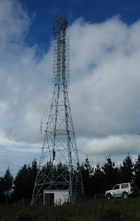
These are broad side collinear arrays, but rather than have resonant reflectors, they have a grid type panel behind the driven elements. The antennas were constructed from steel, the driven element stand offs [The center of a 1/2 wave dipole can be grounded with no ill effects] and dipoles are angle iron, everything - reflector panel, stand offs, and driven elements - are welded and hot dip galvanized as one piece.
There is a north bay, and a south bay [hence the two sets of receive and transmit chains], each panel has three sets of two half wave dipoles fed in phase, there are four of these panels stacked on each side. This adds up to around 18dBi of gain per side?! The beam width is 70 degrees from memory.
Above is a shot of the tower and building, HF wire antenna can be made out, this is used to transmit the monthly NZART official broadcast on 3.900MHz, as well as out on the 2m repeater and 70cm national link system.

Here is a close up with some details marked out, each of the four bays on each side is fed in at the middle set of dipoles, you can make out the crossed phasing lines.
You can also see someone climbing the tower, they moved the 70cm link yagi to Mt Taranaki [Egmont 434.900+] further up the tower as there were some pine trees near by growing up and obstructing the path
These photos are from 2009.
This repeater had very solid coverage of Auckland city, and also south to Hamilton. One of the really interesting things about this 2m repeater and its astronomical antenna gain, it is very sensitive to band conditions once you got around 100 plus miles away. If there was the slightest hint of a band lift, this repeater would shoot up the S meter in strength. Once it pegged at S9+30dB, it was time to start looking for band openings. Some times it would consistently swing in signal level from seconds to minutes, other times it would bottom out and disappear all together..
This repeater could be reliably worked up-to 150 miles in each direction, with the potential for 300 mile separation between stations at the opposite ends of its coverage. Much of this is over less than ideal paths, not bad considering the repeater site is only 1309ft ASL. When band lifts are present the range would easily extend well beyond this.
Now some say this antenna design was borrowed from the Mt Kaukau VHF low band [45MHz and 55MHz] TV broadcast antennas, look at the top, horizontally polarized for TV, but looks familiar doesn't it? The Belmont 147.100+ repeater built by the Wellington VHF Group also used antennas based on this design.


