Thursday, December 24, 2020

Phased Arrays - 40m Verticals no Radials

40m phased vertical array using a pair of verticals based on W6NBC's design from http://www.w6nbc.com/articles/2014-QST40mvertical.pdf. These are essentially a vertical dipole with loading in the bottom leg at the feed-point. In the model I created the total height is around 50ft with the bottom end 5ft above ground level. Not needing radials makes this an attractive design if the space available isn't suitable for radials. 

Phasing a pair of them spaced 1/4 wavelength apart using OVF results in good performance with 3.2 dBi gain at 22.5 degrees elevation with over 20 dB F/B, and 10 dB F/B at 7.0 and 7.2 MHz. Matched SWR is 1.5:1 at the edges. I had tried closer spacings but the F/B and SWR bandwidth is significantly narrower

Opposite Voltage Fed (OVF) arrays were developed by Pekka Ketonen OH1TV. His site contains several examples in different configurations, including details on direction switching and matching networks. OVF uses 1/2 wavelength lines, at a common point where they meet a loading inductor is put in series with one line which makes the array directional, and with a relay electrically reversible. An L match network matches to 50 ohms. The system is simple and can offer much broader F/B and SWR performance compared to coax delay lines or current forcing.

A previous post Phased Arrays - Opposite Voltage Fed (OVF) using a pair of elevated 1/4 wave verticals attempts to explain how the transmission lines, loading and matching networks are "wired up" in the model with virtual connections.

Model file W6NBC_40m_Vert_2El_OVF.ez.

Plots:


What's often remarkable about OVF is how well the F/B and pattern is controlled either side of the design frequency.

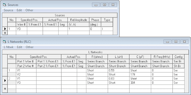
In the model the first L network is the loading inductor for the "rear" element - no shunt is needed so a 1M ohm resistor represents an open circuit.

The direction of the array is switched by changing which side of the loading inductor is fed. The OVF array articles on OH1TV's site show examples. To reverse the direction in the model change V1 to V2 in the second L network. The second L network is for matching, by chance it only needs a 200 pF shunt.

Current chokes are needed where the feed-lines connect to each element in the array, and the polarity is reversed on one of the 1/2 wave lines.

Other phasing systems? Calculating coax delay lines resulted in line lengths too short to reach a common point to enable direction switching. A model using current forcing works but the F/B and pattern shape degrade quicker either side of the design frequency. An example of the difference between current forcing and OVF is shown in Phased Arrays - 40m Twin Half Square.

The Phased Arrays link at the bottom will show other examples using different systems and antenna types, and how they can compare.

Incidentally it was the idea and a QRZ post about phasing a pair of these verticals several months ago that got me started on the path to modeling and better understanding phased arrays and how the different feed systems work.

-----

Models are good starting point, and a way to investigate and better understand antenna systems. These tools can also help guide us to and validate the final result, if a good correlation is observed in the real world then we can have confidence the patterns and other information are accurate.

The models I have created and made available may contain errors, or overlook something someone more experienced can see. I don't claim to be an expert or authority on the subject of antenna modeling or phased arrays. I simply want to further my own knowledge and understanding of antennas which I find fascinating. Comments, suggestions, discussion are welcome - lonney@gmail.com.

This post is one of several on Phased Arrays.

Monday, December 21, 2020

Phased Arrays - 40m Twin Half Square

Phasing up a pair of half square arrays on 40m. 5 dBi at 23 degrees elevation, 10 - 20 dB F/B, beam-width of 70 degrees, and electrically reversible from an antenna needing less than 40ft height, and no radials.

What is a half square? A pair of 1/4 verticals spaced 1/2 wavelength apart with a wire connecting the tops. They produce a low angle (~20 degrees) bi-directional pattern. They can be corner fed directly with coax or voltage fed at the bottom of one leg, and don't need radials. The current nodes are at the tops which makes them quieter on receive compared to conventional verticals. I built one in early 2020 - see 40m half square which also contains links to more information about them.

One downside with half squares is their narrow(er) bandwidth, and as a result when combined with a parasitic reflector or a pair phased together the F/B doesn't stretch as far compared to dipoles, loops or even verticals before it's half of the peak.

Due to the low angle pattern, and narrower bandwidth, they are perhaps better suited to the bottom half of the 40m band where the DX lurks.


Parasitic Array

While not a phased twin half square array, these have been built and used by at least one ham I know.

A cheap 40m DX machine: the twin half square array by VA7ST uses a parasitic reflector based on info by Cebik which can be found at https://www.antenna2.net/cebik/content/ao/ao11.html.

The simplicity of direct coax feeding is retained when using the second half square array as a reflector. The array is made reversible by having two equal length transmission lines meet at a common point, one is connected to the main feed-line, the other is shorted which resonates the other half square as a reflector. The lengths are critical, by using a model and the transmission lines function its easy to discover which length works best, the coax VF and loss figures in the model use the RG-8X spec as an example. In practice VF of coax being used needs to be measured with an analyzer.

Model file 40m_THS_Parasitic.ez using VA7ST's dimensions.

Plots (7.06, 7.10, 7.20 MHz):


Resonance and min SWR are at about 7.1 MHz with a 1.5:1 bandwidth of 70 kHz. F/B figures:

  • 7.06 MHz - F/B 6.9 dB.
  • 7.11 MHz - F/B 15 dB.
  • 7.20 MHz - F/B 9.48 dB.
F/B and SWR range are narrow, the band segment would need to be chosen for performance. SWR would flatten out a bit with feed-line losses etc as I found with the (single) 40m half square I previously built.


Phasing

Advantages of phased arrays include better F/B over wider bandwidths, broader SWR response, and like the parasitic array also electrically reversible.

Phasing adds complexity which will require test equipment, time and effort, possibly a helper to adjust and validate its working as expected.

With the help of tools like EZNEC and Arrayfeed1 or Feed2EL it's possible to create fairly accurate models of the complete system as it would be built. This enables the ability to see how the array performance behaves over its usable bandwidth, and know what to expect.


Coax Delay Lines

These can be calculated using a model with two sources where one has the desired phase shift, in EZNEC Source Data displays the driving impedance for each element, which can be input into Arrayfeed1 to calculate the line lengths.

In the case with this antenna, the driving impedances presented by the half squares result in "No Solution".


More about this feed system at Phased Arrays - Christman Feed System.

The other feed system type that can be calculated with Arrayfeed1 is L Network, which is known as current forcing..


Current Forcing

Current forcing uses 1/4 wave (or odd multiples of) coax lines and an L network to produce the phase shift. An additional L network can be used to match the system to 50 ohms. Since the coax lines meet the L network at a common point the array can be made electrically reversible.

A Half-Sqaure Array for 40 Meters by N2PD uses the current forcing feed-system, and includes info and diagrams for the L networks, and tuning the array.

I was curious to build a model of it and see how it might compare.

There is a process to work through in order to calculate the L network values which involves a few steps and is fairly easy to do:

  • Start with two source (one source has the desired phase shift) EZNEC model to know the driving impedance at each feed-point via Source Data.
  • Input Source Data into Arrayfeed1, calculates the L network values for the phase shift network.
  • Model (or a copy of it) updated using transmission lines and calculated L network values connected via virtual connections.
  • See if it works as expected, how the array behaves over a given bandwidth, and see the resulting current magnitudes and phase-shifts.
  • Include L match matching network for how matched SWR response looks.

I created a model per N2PD's dimensions which were for the 40m CW sub-band. First thing to note is the F/B quoted in the article is optimistic :-) It may be possible to find a deep 30 dB null at a specific elevation angle but the rest of whats going on back there should be considered too, like maintaining an average across a given bandwidth below a given elevation angle.. This is where the fun starts, adjusting the values of things to find the compromise.

Model file 40m_THS_CF.ez.

Plots (7.00, 7.05, 7.12 MHz):


Current forcing offers better F/B compared to a parasitic array, and with a matching network broad SWR. 50 kHz from design frequency F/B falls to half. The phase shift L network has two values to adjust which could mean trial and error to find the best combination in practice.


Opposite Voltage Fed

Opposite Voltage Fed (OVF) arrays were developed by Pekka Ketonen OH1TV. His site contains several examples in different configurations, including details on direction switching and matching networks. OVF uses 1/2 wavelength lines, at a common point where they meet a loading inductor is put in series with one line which makes the array directional, and with a relay electrically reversible. An L match network matches to 50 ohms. The system is simple and can offer broader F/B and SWR performance.

A previous post Phased Arrays - Opposite Voltage Fed (OVF) using a pair of elevated 1/4 wave verticals attempts to explain how the transmission lines, loading and matching networks are "wired up" in the model with virtual connections.

Model file 40m_THS_OVF.ez.

Plots (7.00, 7.10, 7.20 MHz):


OVF appears to improve further, F/B peaks around 20 dB, and at 100 kHz either side of the design frequency the pattern is neat and F/B is around 13 dB at worst. This array would provide good performance between 7.0 and 7.2 MHz with low SWR when matched.

-----

Models are good starting point, and a way to investigate and better understand antenna systems. These tools can also help guide us to and validate the final result, if a good correlation is observed in the real world then we can have confidence the patterns and other information are accurate.

The models I have created and made available may contain errors, or overlook something someone more experienced can see. I don't claim to be an expert or authority on the subject of antenna modeling or phased arrays. I simply want to further my own knowledge and understanding of antennas which I find fascinating. Comments, suggestions, discussion are welcome - lonney@gmail.com.

This post is one of several on Phased Arrays.

Friday, December 18, 2020

Phased Arrays - 40m Inverted Delta Loops

Phasing up a pair of inverted delta loops for 40m, coax delay lines, current forcing, and OVF.

Inverting the loops allows them to hang between trees around 60ft apart and be fed at the bottom. This is convenient since there are no heavy baluns or coax hanging up high as there would be with end supported wire dipoles such as those I explored in Phased Arrays - 40m 2 Element Horizontal.

Modeling phased inverted delta loops turned out to be a little more challenging compared to verticals and dipoles..

In the models I created the inverted delta loops are closer to right angle vs equilateral. This makes the top wire longer which results in slightly more gain, broader F/B and SWR performance when used in a phased array. So far I got a model using OVF working.


Coax Delay Lines

Unable to find a solution that worked.


Opposite Voltage Fed

Opposite Voltage Fed (OVF) arrays were developed by Pekka Ketonen OH1TV. His site contains several examples in different configurations, including details on direction switching and matching networks. OVF uses 1/2 wavelength lines, at a common point where they meet a loading inductor is put in series with one line which makes the array directional, and with a relay electrically reversible. An L match network matches to 50 ohms. The system is simple and can offer broader F/B and SWR performance.

A previous post Phased Arrays - Opposite Voltage Fed (OVF) using a pair of elevated 1/4 wave verticals attempts to explain how the transmission lines, loading and matching networks are "wired up" in the model with virtual connections.

Key details:

  • Top wire height of 45ft.
  • 8.9 dBi gain at 40 degrees elevation.
  • F/B 15 dB or better below 45 degrees between 7.05 MHz and 7.25 MHz.
  • Matched SWR 1.5:1 or better.

A bit more fiddling may improve it further..

Model file 40m_Delta_2El_OVF.ez.


Notes about the OVF model:

Each element has an electrical 1/2 wave coax line meeting at a common point, one line’s polarity must be reversed. VF/loss figures typical for LMR-400 as an exmaple. Current chokes are required at element feed-points if building this.

First L network is a series loading inductor, the shunt is not needed and is open circuit represented by a 1M ohm resistor in the model.

Second L network matches to 50 ohms, its output can be set to V1 or V2 which reverses the direction of the array as it simply switches which half wave line the loading inductor is inserted into.

With OVF arrays either a single or a pair of 1/2 wavelength lines can be used depending on what is more practical, what I have noticed in the models where one line is used F/B is better maintained, and the SWR is bandwidth is broader.

With inverted delta loops it could be done either way as one line will reach the other element, thou the loading/switching/matching network will need to be located at the feed-point of one of the loops. In the model I created the feed-points are about 17ft above ground, the loops can be reshaped to bring the feed-points closer to ground level by narrowing the top wire, when I tried this it appeared to trade away the improvement seen with the original model. Not to say it can't be made satisfactory with experimentation.

-----

Models are good starting point, and a way to investigate and better understand antenna systems. These tools can also help guide us to and validate the final result, if a good correlation is observed in the real world then we can have confidence the patterns and other information are accurate.

The models I have created and made available may contain errors, or overlook something someone more experienced can see. I don't claim to be an expert or authority on the subject of antenna modeling or phased arrays. I simply want to further my own knowledge and understanding of antennas which I find fascinating. Comments, suggestions, discussion are welcome - lonney@gmail.com.

This post is one of several on Phased Arrays.

Thursday, December 10, 2020

Phased Arrays - 40m 2 Element Horizontal

What got me started down the path of two element horizontal arrays was finding a design online for a two element horizontal phased dipole array for 40m using the well known Christman feed system with 84 and 71 degree coax delay lines, the info suggests it works well.

I was curious to see how this system looks when modeled and created one based on the given dimensions - two 63ft dipoles spaced 1/4 wavelength apart at a height of 45ft.

VA7ST has a handy Christman phasing calculator which calculates the 84 and 71 degree line lengths with the velocity factor of the coax being used.

With EZNEC the delay lines can be entered using the transmission lines function, and connected to the source using virtual connections - DW_Christman.ez.

Plots:


Primary (black) is 7.15 MHz, blue 7.05 MHz, and green 7.25 MHz.

The forward gain is fairly good at near 8 dBi, but the F/B ratio is low at around 7 dB.

Looking at the current magnitudes and phase in EZNEC the phase shift is about 105 degrees, and the current magnitudes are not equal (or close) at segment 25 (feed-points) which results in low F/B. The info given doesn't indicate if the polarity of one of the coax lines is reversed or not, reversing one further reduced the performance.

As noted in ON4UN's Low Band DXing book (5th edition, chapter 11, section 3.4.2) the 84 and 71 degree lines are calculated for a pair of ground mounted 1/4 wave verticals spaced 1/4 wavelength apart, and is derived from the feed-line impedance (50 ohm) and driving impedance of each element in the array.


How to improve it?

Playing with a 2 source model where the phase shift can be directly entered I found around 115 degrees peaks the F/B with a pair of horizontal dipoles spaced 1/4 wavelength apart.

I then wondered how much this could be improved upon and got reasonable results with F/B 15 dB or better and good SWR bandwidth with an L match using two different feed systems..


Coax Delay Lines and Current Forcing

Coax delay lines can be correctly calculated using a couple different tools to calculate the drive impedances.

Until recently I thought I had a solution using coax delay lines, but it was the result of making a mistake mixing up the leading and lagging drive impedances inputted into Arrayfeed1 or Feed2EL, somewhat surprisingly it almost works when the polarity of one coax line is reversed in the model!

I need to re-write this page with new examples, until then Phased Arrays - Christman Feed System has two examples on how to calculate these:

  1. Coax Delay Lines, this array type has no solution with 50 or 75 ohm coax, there might be a solution with 25 ohm (50 ohm paralleled) or 100 ohm coax, try it and see.
  2. Current Forcing, the 20m dipoles example could easily be scaled to 40m.


Opposite Voltage Fed

Opposite Voltage Fed (OVF) arrays were developed by Pekka Ketonen OH1TV. His site contains several examples in different configurations, including details on direction switching and matching networks. OVF uses 1/2 wavelength lines, at a common point where they meet a loading inductor is put in series with one line which makes the array directional, and with a relay electrically reversible. An L match network matches to 50 ohms. The system is simple and can offer broader F/B and SWR performance.

A previous post Phased Arrays - Opposite Voltage Fed (OVF) using a pair of elevated 1/4 wave verticals attempts to explain how the transmission lines, loading and matching networks are "wired up" in the model with virtual connections.


Key details:

  • Height 13.75 m / 45 ft.
  • Element length 19.65 m / 64.4 ft (#12 uninsulated wire).
  • Element spacing 10 m / 32.8 ft.
  • Loading inductor 3.2 uH.
  • The polarity of one of the 1/2 wave lines must be reversed when using two.
  • Gain 8.9 dBi, F/B 15 dB or better (under 60 degrees).


Model file: 40m_OVF_Horz_45ft.ez

Plots:


Primary is 7.15 MHz, blue 7.05 MHz, and green 7.25 MHz.

Don't get too excited about the 30 dB odd of F/B, it's a very specific elevation angle where this occurs. Attention should be given to overall shape of the pattern at the back half below about 60 degrees (3 notches up from 45 degrees). Below this point the F/B is 15 dB or better.

The gain, F/B, and pattern shape is very well controlled across the 40m band.

The SWR plot is in 100 kHz steps. Matched SWR is 1.5:1 or better across nearly the whole band except for the top 20 kHz.

There is also a relationship between the element lengths and the loading indicator value that results in better F/B ratio stability across the band which I discovered by trial and error.

Note that the polarity of one 1/2 wave line must be reversed.

Some thoughts on building this array:
  • The model would need to be updated if elements using insulated wire or tubing are used. 
  • Remove all but one dipole from the model, note its resonant frequency and impedance. Put a dipole up in each position separately adjust to match the single dipole in the model.
  • Coax VF/loss is for LMR-400. 1/2 wavelength at 7.15 MHz with VF 0.84 = 17.6 m, I found increasing to 18m length and tweaking the loading inductor a little in the model helped keep SWR under 1.5:1 at the bottom end of the band. The VF of the coax being used to build the array would need be measured and entered into the model with adjustments as needed to account for it.
  • At a height of 45ft the lines from each dipole will conveniently reach each other at ground level according to a triangle calculator.
  • 1:1 baluns/current chokes should be used at the dipole feed points with any additional electrical length they add factored in.
  • The direction of the array can be reverse simply by switching which line the loading inductor is inserted into where they meet.
  • The loading inductor value in the model is critical as changes can drastically change F/B. This might be a sticking point when building the array is adjusting this and validating its right?
  • OH1TV notes in at least one of the OVF articles that keeping the leads and lengths as short as possible in the switching and matching network etc is important as they add inductance.

With OVF arrays a range of element spacings work from near 1/8 out to at least 0.35 wavelengths. The closer the spacing the narrower the operational bandwidth. 

1/4 wave spacing was chosen as this results in a matched SWR under about 1.5:1 across the band.

The weight issue with end supported dipoles and the balun and coaxing hanging could possibly be solved if the system can be/is reworked with using 450 ohm ladder line for the half wave lines.


The K5UA 40 meter Phased Array

The downside to using coax delay lines, or loading networks (OVF) is the complexity and having the test equipment, skill, time, trial and error to validate what you built matches what the model predicts.

The K5UA 40 meter Phased Array bypasses all of that and simply runs two equal lengths of coax from each dipole to the shack and into an adjustable phasing network, then an antenna tuner and into the the amp/rig. Varying the phase shift changes the elevation angle of the null to the rear allowing the operator to optimize the SNR (signal to noise ratio) of the desired signal.

The weight issue with end supported dipoles and the balun and coaxing hanging could be solved with equal lengths or 1/2 wave lengths of ladder line hanging to or near ground level then 1:1 balun/choke into equal lengths of coax back to the shack.


Conclusions, and which one?

Good question.

The K5UA system makes it simple, just build the phasing network and get an ATU.

I like the OVF array, it's an elegant system.

As with any of these a means of validating the tuning and performance using current probes and far field testing with a signal source to validate the F/B performance.

-----

I recommend reading the Phased Arrays chapter in ON4UN's Low Band DXing book (which now appears to be out of print!), it is a deep dive into the subject, and a lot of it is way over my head.

There are a couple important details about phased arrays that should be known:

The current magnitudes at the element feed points need to be equal, and with the right amount of phase shift. If either of these are not right, things fall apart.

With coax delay lines the phase shift of a transmission line is only equal to its electrical length when the line is terminated into its characteristic impedance. Which is pretty much never in a phased array, so we cant cut a line for x degrees between two antennas and expect it to work.

Delay lines calculated for one type of phased array can not be transplanted into another type as the driving impedances of the elements in the array will be different, even changing the height of an array can/will alter the driving impedances.

-----

Models are good starting point, and a way to investigate and better understand antenna systems. These tools can also help guide us to and validate the final result, if a good correlation is observed in the real world then we can have confidence the patterns and other information are accurate.

The models I have created and made available may contain errors, or overlook something someone more experienced can see. I don't claim to be an expert or authority on the subject of antenna modeling or phased arrays. I simply want to further my own knowledge and understanding of antennas which I find fascinating. Comments, suggestions, discussion are welcome - lonney@gmail.com.

This post is one of several on Phased Arrays.

Thursday, November 19, 2020

Phased Arrays - Opposite Voltage Fed (OVF)

Opposite Voltage Fed (OVF) arrays were developed by Pekka Ketonen OH1TV. His site contains several examples in different configurations, I've linked them here for convenience:

40. OVF 2-el phased vertical for 40m   2011 is probably the easiest one start with, for 40m a pair of 1/4 wave verticals is one of the easier and cost effective ways to make some gain on this band. I decided to model this one to learn more about it based on the dimensions in the article.

Models: 40m_2ElGP_OVF.ez, and 80m version I scaled 80m_2ElGP_OVF.ez.

I got with-in 0.1dBi of the plots in the article. I've also overlaid plots at 7.0 and 7.2MHz since the article also shows plots at these frequencies. My model favors the lower end of the band slightly, so there is a small detail in there somewhere that is different which some tweaking would fix.

The system maintains a good pattern and SWR over a wide bandwidth, both desirable characteristics. Centered on 7.075MHz, SWR at is 1.2:1 at 7.0 and 7.175MHz, rising to 1.5:1 at 7.26MHz and 1.73:1 at 7.3 MHz.


I'm going to attempt to explain how this thing is wired up in EZNEC. It took "a while" for me to wrap my head around defining the transmission lines, the loading inductor, and lastly the L network for matching to 50 Ω.

How its defined here resembles the article where one 1/2 wave line is used, and the loading inductor 1.66 uH is inserted at the other end of the line where the east element is fed and the system is matched.


Transmission Lines:
  • No 1. 1/2 wave line connected to wire 1 (the west element), ends at V1.
  • No 2. Very short connection (10cm/4") to wire 5 (the east element), ends at V2.
  • V1 and V2 are virtual connections, these can be used to connect to other things such as L networks, sources, and make interconnections.
  • The VF and loss figures are for LMR-400.


L Networks:
  • No 1. The 1.66uH loading inductor is connected in series with V1. A shunt is required in the L network but not used so I input 1M ohm resister to make it "open circuit". The other side of the inductor is connected to V2.
  • No 2. The matching L network "input" is V3 at the bottom, this is where the source is or coax back to the rig would be connected. When the "output" of the L network is connected to:
    • V2, puts the loading inductor in series with the west element (wire 1) the antenna fires east (as shown above).
    • V1, puts the loading inductor in series with the east element (wire 5) the antenna fires west.

If we look at 40. OVF 2-el phased vertical for 40m   2011 - page 3, all we're changing is which side of the loading inductor we are connecting the output of the matching L network to.

I used this RF Impedance Matching Calculator to calculate the L network values for a 50 Î© match based on the Src Dat (Source Data) in EZNEC.

Other array types OVF can work with include:


What is OVF phasing? 17. Opposite voltage fed array 2009 - page 12, and 55. 40m OVF stack at OH2BH  2014 - page 4 explain how OVF works.

ON4UN's Low Band DXing 5th edition chapters 3.4.9, and 3.4.10.4 cover OVF in detail, and notes that this system had not been published before. The book covers the math and includes spreadsheets to calculate the component values or two and four element arrays in 4-square configuration.

I struggled to make sense of it and emailed OH1TV with some questions about the two element arrays. I got a quick reply which made it simple, use an EZNEC model, and find the values through trial and error.

The elements need to be resonant above the operating frequency, the loading inductor detunes the "rear" element making it a reflector. With trial and error the best element length and inductor values can be found which peaks the F/B, current magnitudes are equal in each element (Src Dat in EZNEC), and the pattern degrades symmetrically either side of the design frequency - the sweet spot is found.

-----

Models are good starting point, and a way to investigate and better understand antenna systems. These tools can also help guide us to and validate the final result, if a good correlation is observed in the real world then we can have confidence the patterns and other information are accurate.

The models I have created and made available may contain errors, or overlook something someone more experienced can see. I don't claim to be an expert or authority on the subject of antenna modeling or phased arrays. I simply want to further my own knowledge and understanding of antennas which I find fascinating. Comments, suggestions, discussion are welcome - lonney@gmail.com.

This post is one of several on Phased Arrays.

Thursday, October 29, 2020

Phased Arrays - Christman Feed System

How to calculate it, and current forcing with examples below.

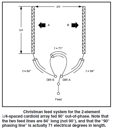
The Christman feed system is well known as using a pair of 84 and one 71 degree line connected together to achieve a 90 degree phase shift with a pair of 1/4 wave ground mounted verticals spaced 1/4 wavelength apart. This produces a directional pattern with a good F/B ratio.

This is a popular choice since it's easy to cut some coax and connect it up!

VA7ST has a handy Christman phasing calculator that will output the cable lengths for a given frequency.


Christman feed system 1/4 wave verticals


Does it just work with other array types?

No, but that doesn't stop some from wanting it to work :-)

The coax lengths must be specifically calculated to deliver equal current magnitudes (with two element arrays) and the right phase shift based on the drive impedance of each element in the array. If these two requirements are not met, then the front to back (F/B) falls and the performance suffers.


How are these coax delay line lengths calculated?

  • Self impedance - impedance of one element by it self is measured.
  • Coupled impedance - second element is added, impedance at one element is measured.
  • Drive impedances (of each element) - calculations are done with self and coupled impedances in-conjunction with the desired current magnitude and phase shift.
  • Once the drive impedances are known, the coax delay line lengths, or L-Network values for use with 1/4 wave lines (current forcing) can be calculated.

The calculations are complex, fortunately there are tools to help do these calculations.

The spreadsheet Drive2EL will calculate the drive impedances from the self and coupled impedances, and phase shift. Since it only uses formulas it should also work in other spreadsheet applications such as Libre Office Calc (free). Drive2EL uses (with permission) parts of the formulas from ON4UN's Low Band DXing 5th Ed Excel spreadsheet "w1mk-on4un-oh1tv-arrays.xls" (which can calculate multi-element arrays), and provides a simplified interface for two element array calculations to make it easier.

The spreadsheet Feed2EL will calculate the coax delay line lengths or current forcing L network values, it also includes series and L network matching calculators, and a library of coax cable types. However it requires Microsoft Excel to run the macros it uses.

With out Excel, an alternative would be to use the Windows app Arrayfeed1 (PDF of manual) which only does the coax delay line length and current forcing L network calculations, other calculators would need be used for the series or L network matching - these can be found online.


Practical Examples

Jump to Christman, Current Forcing, Opposite Voltage Fed.

How to work through this calculation process using EZNEC models to measure the self and coupled impedances, and the two spreadsheets to crunch the numbers.

This demonstrates the process one would use when building an array. A two source EZNEC model can also be used to see the calculated drive impedances directly which speeds up the modeling process by eliminating the steps with Drive2EL, this is noted in each example.

When simply experimenting with models using transmission lines I set the VF to 1 and omit the loss figures to keep things simple, then in the final iteration I might add those details in to see the effects.

In these examples for completeness I included the coax VF and loss figures in the models from the library included with Feed2EL. Any final designs which would then be built should include as much accurate detail as possible in the model.

The VF of the coax being used when building feed systems should be measured with an analyzer as the mfg spec is approximate and can vary, it can even vary by frequency! See TLDeails figure 3.

EZNEC models assume various ideals (it is a simulation after all and the outputs are only as accurate as the inputs), the transmission lines for example are virtual and will never carry common mode currents.

In practice 1:1 current chokes/baluns should be used at the feed point of each antenna to ensure equal and opposite currents are forced into the antenna and common mode currents are blocked. The choke also needs to preserve total line length and impedance! My Antennas / Baluns / Feedlines page has links to information on current chokes.

Here are two examples, one using Simplest (coax delay lines) with 40m elevated verticals, and another using L Network (current forcing) with 20m horizontal dipoles.

These examples are just that, examples. They may not result in the best properties or performance possible, the goal here is to show the process as a set of steps.

Note: The voltages, currents, and magnitudes etc displayed by EZNEC are with the power level set to 1000 watts in EZNEC > Options > Power Level. Options > Save As Default will store this change.


Christman (Coax Delay Lines) with 40m Elevated Verticals

This uses 50 ohm coax for the delay lines, and a 75 ohm coax section to match the system to 50 ohms.

The vertical used as staring point is elevated 3 meters / 9 ft above average ground, and has 3 evenly spaced radials created using the Create > Radials function based on wire 3 which calculates the geometry to get the angle and lengths right.

Note: As with the second example below using horizontal dipoles on 20m (which I did first when writing this), I found the array may perform better when it is tuned to resonance when coupling with the second element in position but not connected. In this example I have accounted for that, the coupled reading will show as resonant (no reactance), the self impedance reading will show the antenna resonant above the design frequency. Is this a rule of thumb with coax lines or current forcing? I'm not sure, but it's something I noticed. 


Open the Drive2EL spreadsheet.

Open 40m-1-GP.ez.

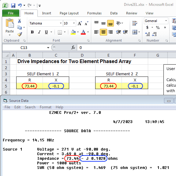
Click Src Dat to see the source data self impedance, and enter these values into Drive2EL both Self Element 1 Z and Self Element 2 Z.

Note: When building an array in practice each antenna on its own may have a different self impedance, so each should be measured separately.

Input EZENC source data into Drive2EL


The next two steps are copying and rotating wires, 40m-2-GP-1-Wires.ez has this done.

Add the 2nd element in the array using the copy wires command, offset X by 10.75, and uncheck Copy sources, loads, TL stubs.

EZNEC copy wires


Rotate wires 6 through 10 to get the 2nd vertical correctly orientated.

EZNEC rotate wires


View Ant should look like this (dual 3 radial layout is borrowed from this OVF array by OH1TV):

ENZEC elevated 40m verticals antenna view


Click Src Dat to see the source data coupled impedance, and copy the values into Coupled Element Z.

Input EZENC coupled impedance into Drive2EL


In Drive2EL Element 2 I and Phase change phase to -90, leave Element 1 I and Phase as 1 and 0.

The drive impedances for each element are now displayed.

Drive2EL showing calculated drive impedances


EZNEC Drive Impedances

-----

Note: If simply experimenting with models we can skip to this step and use a two source model to see the drive impedances calculated directly by EZNEC.

The optimal phase for the array type and height can be found by experimenting with a two source model to find what seems good or suits a given goal and constraints, then plug the drive impedances into Feed2EL or Arrayfeed1 to calculate the coax lines or L network values

When building the array the above process of taking measurements from the physical antenna elements should be done to confirm the model is accurate and/or to account for other factors in the environment that may affect the real world results.

-----

In EZNEC add a second source to wire 6, and change the Phase to -90

EZNEC add second source


Click Src Dat, the drive impedances are shown for each element, these are fairly close to what Drive2EL calculated.  After making inquiries, one of the authors of the phased array chapter in the ON4UN book noted the formulas in the spreadsheet included with the book are based on simple equations and models, where-as EZNEC/NEC2 calculation are based on complex models, they also noted that it's more important to get the currents correct in the array (by measuring them) than worry about small differences the impedances.

EZNEC showing drive impedances


Open Feed2EL, set type to Simplest, enter the frequency 7.15, enter the drive impedances into Element 1 Z and I and Element 2 Z and I respectively, Phase -90.

Click Find Solution, the coax length values are calculated taking into account the type, impedance, and VF of the coax type used (Library), Belden 9258 RG-8X is selected.

If no solution is found, changing to 75 ohm coax will sometimes work. If not an L network (current forcing) should give a solution.

Feed2EL coax line lengths
(click for larger image)


Note: To make the direction switchable in practice (per the Christman diagram at the top of the page), the shorter Line 1 length (94.36 degrees / 8.87 m) must reach each other at a common point from each element, the Line 1 length is then subtracted from the Line 2 length (185.15 degrees / 17.404 m), the difference (90.79 degrees 8.53 m ) is switched from one side to the other (adding back up to 185 degrees / 17.404 m) to reverse the direction of the array.

With the coax length values calculated, the EZNEC model can be updated to resemble the antenna system as it would be constructed in practice to see how it will perform over a given bandwidth.

V1 (virtual connection) becomes the junction where both lines meet and connect.

Delete source 2, change the remaining source to V1.

Add two transmission lines using the calculated values, the line from the first vertical (wire 1) and the line from the second vertical (wire 6  both connect to V1.

EZNEC update model with coax lengths
(click for larger image)

40m-2-GP-2-CDL.ez has the source updated and transmission lines added as above.


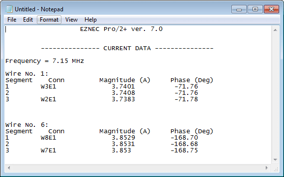
Click Currents and note the magnitudes on wire 1 and 6 (fairly close), and the phase (about 96 degrees), here I've just shown those two wires for convenience.

The currents shown are with the power level set to 1000 watts in EZNEC > Options > Power Level.

EZNEC currents


Click FF Plot, on the 3D view window click View > Show 2D Plot to see Elevation and Azimuth plots.

Check the pattern stability over a frequency range, here I've saved and added the traces for 7.05 and 7.25 MHz.

EZNEC elevation and azimuth patterns


When I compared to using 2 x 84 and 71 degree lines, the F/B has dropped, and the Currents window showed the magnitudes are far from equal.

EZNEC patterns calculated lines vs 2 x 84 / 71 degree lines


Click Src Dat, SWR is around 1.5:1, we can get that down using a series matching section of 75 ohm coax which Feed2EL will calculate.

Use series section calculator on the on the Feed2EL sheet to match to 50 ohms, add the transmission lines and virtual connections, update source virtual connection, Belden 9258 RG-8X 50 ohm,  Belden 9116 RG-6 75 ohm coax is selected. Run SWR sweep.

Feed2El series matching
(click for larger image)

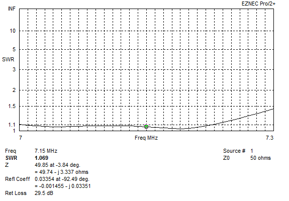
Matched SWR plot

40m-2-GP-3-CDL-Matched.ez has the matching sections added as above.

Overall this array looks good, the pattern and F/B degrades maybe more than we'd like at +/- 100 kHz, this is a limitation of using coax delay lines. However with the series matching also using coax, this array is phased and matched with coax keeping things simpler.


L Network (Current Forcing) with 20m Horizontal Dipoles

Current forcing is used in this example, this uses a pair of 1/4 wave lines and an L Network where they meet - this will work when a solution using coax delay lines (Christman) cant be found.

Note: With this array type Feed2EL does not find a solution with 50 or 75 ohm coax delay lines. 100 ohm, 37.5 or 25 ohm (e.g. 75 or 50 ohm coax ohm in parallel with the cores joined) will find a solution for coax lines, the series matching finds a solution with 25 ohm, so it would be possible to feed and match this array type using 50 ohm coax paralleled to make 25 ohm line.

This shows with some imagination a solution is possible, however I wanted to show an example using current forcing with commonly available coax.


Open the Drive2EL spreadsheet.

Open 20m-1-Dipole.ez, the dipole is 10 meters / 32.8 ft above average ground, and is resonant at 14.15 MHz. 

Click Src Dat to see the source data self impedance, and enter these values into Drive2EL both Self Element 1 Z and Self Element 2 Z.

Note: When building an array in practice each antenna on its own may have a different self impedance, so each should be measured separately.

Input EZENC source data into Drive2EL


Add the 2nd element in the array using the copy wires command, offset X by 5.3, and uncheck Copy sources, loads, TL stubs.

EZNEC copy wires


Click Src Dat to see the source data coupled impedance, and copy the values into Coupled Element Z.

Input EZENC coupled impedance into Drive2EL


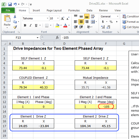
In Drive2EL Element 2 I and Phase change phase to -105, leave Element 1 I and Phase as 1 and 0.

The drive impedances for each element are now displayed.

Drive2EL showing calculated drive impedances


EZNEC Drive Impedances

-----

Note: If simply experimenting with models we can skip to this step and use a two source model to see the drive impedances calculated directly by EZNEC.

The optimal phase for the array type and height can be found by experimenting with a two source model to find what seems good or suits a given goal and constraints, then plug the drive impedances into Feed2EL or Arrayfeed1 to calculate the coax lines or L network values.

When building the array the above process of taking measurements from the physical antenna elements should be done to confirm the model is accurate and/or to account for other factors in the environment that may affect the real world results.

-----

In EZNEC change add a second source to wire 2, and change the phase to -105, this amount of phase shift was found via some trial and error to see what gave the better end result for the given height above ground.

EZNEC add second source


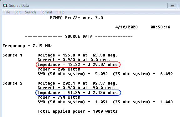
Click Src Dat, the drive impedances are shown for each element, these are fairly close to what Drive2EL calculated. After making inquiries, one of the authors of the phased array chapter in the ON4UN book noted the formulas in the spreadsheet included with the book are based on simple equations and models, where-as EZNEC/NEC2 calculation are based on complex models, they also noted that it's more important to get the currents correct in the array (by measuring them) than worry about small differences the impedances.

EZNEC showing drive impedances


Open Feed2EL, set type to L Network, enter the frequency 14.15, enter the drive impedances into Element 1 Z and I and Element 2 Z and I respectively, Phase -105, Place Network On Line 2.

Click Find Solution, the L network values are calculated, and the 1/4 wave lines taking into account the type, impedance, and VF of the coax type used (Library), Belden 9116 RG-6 75 ohm coax is selected.

Feed2EL L network values
(click for larger view)


With the L Network values calculated, the EZNEC model can be updated to resemble the antenna system as it would be constructed in practice to see how it will perform over a given bandwidth.

Delete source 2, change the remaining source to V1 (virtual connection).

Add two transmission lines, one to each dipole, the line from dipole (wire) 1 connects to V1, and the line from dipole (wire) 2 to V2 using the calculated values.

Add an L network, and enter the calculated values for the series and shunt.

EZNEC update model with L network and 1/4 wave lines
(click for larger view)


20m-2-Dipoles-1-CF.ez has the source updated, lines and L network added.


Click Currents and note the magnitudes the center segment 26 of each wire, and the phase, here I've just shown the 3 center segments of each wire for convenience.

The currents shown are with the power level set to 1000 watts in EZNEC > Options > Power Level.

EZNEC currents


Click FF Plot, on the 3D view window click View > Show 2D Plot to see Elevation and Azimuth plots.

Check the pattern stability over the frequency range, here I've saved and added the traces.

EZNEC elevation and azimuth plots


When I compared to using 2 x 84 and 71 degree lines, the F/B has mostly gone, and the Currents window showed the magnitudes are far from equal.

EZNEC patterns calculated L network vs 2 x 84 / 71 degree lines


Click Src Dat, SWR not great. Use L network calculator on the on the Feed2EL sheet to match to 50 ohms, add L Network, update source virtual connection, run SWR sweep.

EZNEC match with L network
(click for larger view)


Matched SWR plot


20m-2-Dipoles-2-CF-Matched.ez has the matching L network added.

Overall the array favors the lower end of the 20m band for pattern stability and SWR response when matched.

Some experimentation would be needed to optimize the pattern response across the band better depending on what we want, or how OCD we are :-)

I tried tuning the dipoles to resonance at the target frequency when coupled, as the coupling had lowered their resonance (coupled reading above showed a positive (+ J) reactance indicating that it is inductive or "too long" at 14.15 MHz). When I did this the elements were shortened to 10.115 meters, after re-calculating the phase shift L network the F/B held up better further up the band. After updating the matching L network values, the SWR sweep improved 1.17:1 at its highest.

Using models helps discover these characteristics which can then be accounted for when setting out to build the array for example.

ARRL Antenna Book covers current forcing in detail (Chapter 6 in 24th Edition).

G3WZT Phased Verticals - designed and built a 3 element vertical array using current forcing.

NA6O 40m Phased Vertical Array - 2 element elevated vertical array using current forcing.


Other Feed Systems?

ON4UN's Low Band DXing book dives deep into detail on phased arrays and different feed systems.

Opposite Voltage Fed

One notable feed system that does not appear to be widely known is Opposite Voltage Fed (OVF) developed by OH1TV.

OVF uses 1/2 wavelength lines (voltage forcing), and a loading inductor or capacitor in series with one element. Since the lines are 1/2 wave the load can be placed at either end making for convenient direction switching.

From my modeling experiments with OVF it works with all element types (verticals, dipoles, loops, half squares), has a wider operational bandwidth, better pattern stability, and when matched a fairly good SWR response across the band.

 More information about this system with examples can be found at:


Acknowledgments 

  • AC6LA - Feed2EL (and other amazing tools).
  • ON4UN's Low Band DXing - spreadsheet formulas used in Drive2EL.
  • VK4NRO - Alerting me to the fact drive impedances can be calculated from the self and coupled impedances, which resulted in Drive2EL and a complete re-write of this page!


-----

Models are good starting point, and a way to investigate and better understand antenna systems. These tools can also help guide us to and validate the final result, if a good correlation is observed in the real world then we can have confidence the patterns and other information are accurate.

The models I have created and made available may contain errors, or overlook something someone more experienced can see. I don't claim to be an expert or authority on the subject of antenna modeling or phased arrays. I simply want to further my own knowledge and understanding of antennas which I find fascinating. Comments, suggestions, discussion are welcome - lonney@gmail.com.
This post is one of several on Phased Arrays.