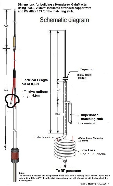
I ran across this interesting antenna design on VK5ST QRZ bio after completing a 10m FT8 contact yesterday.
Ok, that got me interested, center fed verticals don't get much attention. A while ago I discovered on my own they are pretty good, much better elevation pattern stability compared to end fed over a ground plane, quieter on receive and they perform quite well in my opinion :-)
As with all antenna designs, it's always good to model them to see what we can learn, and what to expect before getting too excited..
When modeled 15ft above average ground it has a shade more gain at 2.6 dBi, maybe half a dB more quickly looking at a conventional 5/8 ground plane model I have.
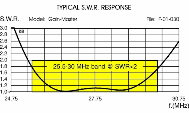
The SWR response is quite broad, 2 MHz bandwidth at 1.5:1 or better. This would flatten out even more with feed line losses etc. This antenna could easily cover the New Zealand 26 MHz CB band, 27 MHz CB band, and the bottom of 10 meters!
Model: Gain-Master
I had to change the capacitor value to 14 pF which resonated the antenna at 27.3 MHz and provided a very near perfect 50 ohm match leaving the stub length and position as is.
Transmission line 1 is the length between where stub attaches and the capacitor.
Transmission line 2 is the shorted stub length.
V1 where they meet is the 50 ohm feed-point (source).
----------
How does this antenna work?
Specifically the function of the capacitor and stub to match it.
The good thing about antenna modeling, is we can take antennas apart and put them back together again to learn how they work by making a change and looking at the result.
At the center of a split 5/8 wavelength dipole in EZNEC we see 180 + J 420 ohms:
- Top half is wire extending beyond capacitor, bottom half is the outside of the coax shield down to the choke.
- Capacitor in series with the center conductor tunes out the inductive reactance leaving 180 ohms resistive.
- 50 ohm point is found where the stub attaches, the coax from this point running down to the choke is matched to 50 ohms.
- The length of coax between the end of the stub (hanging off the side) and the capacitor forms the total stub length.
- Assuming I got my math right: The length of the stub is a 1/4 wavelength at 25 MHz when the VF of 0.66 is taken into account! Why this length I'm not sure, we can shorten the stub to be a 1/4 wave at 27.2 MHz and with some trial and error find the 50 ohm point and a cap value that gives a 50 ohm match.
From there the antenna is simply a center fed vertical dipole made out of coax. The wire beyond the capacitor is the top half, the coax shield down to the choke is the bottom half, the stub hanging off the side would appear to have little to no effect.
An example of a 1/2 wave vertical dipole made of coax and wire is K9YC's Vertical Dipole, except being a 1/2 wave it doesn't need a matching network as its resonant on its own and close enough to 50 ohms. A simple series matching section could make it perfect. It wont have the same broad bandwidth however. Uses ferrite for the choke which is a much better choice especially for high power use.
As for the choke, its size and number of turns isn't close to anything on the chart at http://www.karinya.net/g3txq/chokes/. An analysis would need to be done on the Gain Master choke to better understand it. Since it remains an unknown I would personally use a ferrite choke such as those used by K9YC's vertical dipole as an example. For more about air core chokes see Air Core Coax Chokes: Good, Bad and Ugly by VE3VN.
Getting back to the stub for a moment, using a shorted 1/4 stub I've seen used as a technique to broadband inverted L antennas on 160m - http://mobileers.com/main/wp-content/uploads/2017/01/N9LYE-22L22.pdf (web.archive.org - original is gone). Experimenting with the model as a 5/8 split dipole (source in the center) and the capacitor to get 180 ohms resistive, adding a 1/4 wave stub by it self does have a broad-banding effect, but that is likely a bonus secondary function of the matching stub in the Gain Master design.
----------
I ran the model through AutoEZ to use variables and the optimizer, it made very incremental changes to the values for the capacitor, the stub length and position - basically nothing to be gained, this design is perhaps already quite optimized!
Adding a 1 to 5 meg ohm 5W metal film resistor across the cap to bleed off static buildup also a good idea.


