Showing posts with label Antenna_Models. Show all posts

Sunday, December 17, 2023

Cebik Pages Update


As noted, things have been tidied and improved, updated to syntax correct HTML with a single CSS file, broken links fixed, some missing content found and added back in. A useful addition is the topics index which makes it easy to find all related pages on a subject, and see them all listed in one place.

I started working on this a few weeks ago when I learned that ON5AU who hosted the only known complete copy had become SK.

After I started looking at the Cebik pages, one thing lead to another, and the end result was significant update which I think was needed considering how useful this is to many.

Happy Holidays!

Monday, February 6, 2023

40m 1/3 Wave Elevated Vertical 50 Ohm

40m elevated vertical (1/3 wave) using 40ft / 12m Spiderbeam pole, 3 x 16ft / 4.9m radials, 50 ohm feed.

EZNEC 40m 1/3 wave vertical antenna view


We can feed a vertical off-set by extending the vertical element and shortening the radials to raise the feed-point impedance while maintaining resonance.

The radials must be electrically isolated from a metallic mast (if used), and a high quality 1:1 current balun to isolate the coax shield from the antenna system, I'm using a Balun Designs 1115t.

Elevation Plot:

EZNEC elevation plot


SWR Plot:

EZNEC SWR plot


In this case making use of a 40 ft / 12 meter Spiderbeam pole mounted 10 ft / 3 m above ground on the 2nd level deck at the back of the house.

Modeling this using bare 12 AWG wire, the radial length to achieve resonance was 23 ft / 7 m. At least part of the reason my radials ended up shorter will be because I used plastic coated wire, and the vertical wire is attached to a fiberglass pole, but there may be something else having an effect..

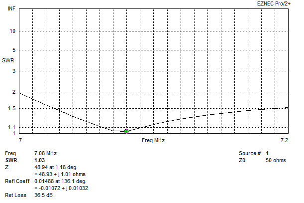
However after trimming the radials for resonance the analyzer showed a perfect match:

RigExport analyzer showing complex impedance


The analyzer hung off the balun with a 6" jumper, since the SWR didn't change after connecting the feed-line is an indication the balun is doing its job.

The SWR response turned out to be more broad-banded than predicted according to the IC-7300, it covers the whole 40m band only rising to 1.5:1 at 7.3 MHz (feed with 70 ft of LMR-400):

IC-7300 SWR plot


Photo of the antenna:

Picture of 40m 1/3 wave vertical


The longer radiator moves the current maximum slightly higher above surrounding clutter.

One radial runs out near the end corner of the house, one out to a tree in the back yard, and one along the under side of the deck, this also allowed mounting the balun out of the weather. With the shorter radials I was easily able to maintain ideal symmetry.

Compared to a 1/4 wave ground plane model same height above average around with four radials, the 1/3 wave vertical peak gain is 0.2 dB less but one degree lower at 22 degrees.

Some or more of that 0.2 dB might be gained back with the higher current maximum in the real world environment with ground clutter, and broader 1:1 SWR vs 1.3:1 or higher with a ~36 ohm 1/4 wave. Either way a negligible trade off (if any) for a much more convenient radial configuration and 50 ohm feed. Field strength readings would be the next step.

Noise floor is not too bad at S4 to S5, compared to S3 to S4 on my 130 ft doublet at 55 ft height.

We'll see how it works out :-)

Model file: GP-40m-40ft.

Sunday, January 22, 2023

40m 2 Element Delta Loop

Parasitic (driver + reflector), reversible, direct 50 ohm feed, equal length 75 ohm sections for matching and the open stub long enough to reach a common switching point.

Recently during the middle of the day I noticed a local station here on the US west coast spotting EU stations on 40m FT8 via psk reporter. This is fairly unusual due to day time D layer absorption, but not impossible. I emailed asking for more info about the antenna they were using, they replied saying they had built a two element delta loop array based on 40 Meter Parasitic Delta Loop Array by W8WWV.

Trying to model this by hand in EZNEC the results were not great, especially trying to get a 50 ohm match. Since there are interactions with element spacing, resonance, etc - change one thing it throws off several others.

Decided to give this problem to the optimizer in AutoEZ. Optimizing for gain and direct 50 ohm feed, I let the optimizer adjust the length of the bottom wire, the height of both loops, and the feed positions symmetrically, and vary two equal lengths of 75 ohm coax for the open stub and matching section to keep it simple.

I was pleasantly surprised when AutoEZ found a perfect solution using two equal length sections of 75 ohm coax that will easily reach a common point, and provide a direct 50 ohm feed!

Searching around for information on designs using switched open stubs, there are a few which use 3/8 λ open stub for the reflector.

Interesting to note, the starting model I had used equilateral triangles (what I happened to have), the optimizer settled on right angle triangles (very close at 89 degrees). Agrees with accepted wisdom for vertically polarized deltas, see SCV Polarized Wire Antennas: The Delta Branch - L.B. Cebik.

On to the details..


EZNEC antenna view

Item

Measurement

Horizontal wire height above ground

3 m / 9.8 ft

Horizontal wire length

18.28 m / 60 ft

Height to apex above ground

12.31 m / 40.3 ft

Side wire length

13.04 m / 42.78 ft

Element spacing

7 m / 23 ft

Feed position up side

16.3% or 2 m / 6.5 ft

75 Ω coax length from each element

13.74 m / 45 ft (VF=1)


Each 75 ohm line meets at a common point:

  • 75 ohm line connected to the driver matches the system to 50 ohms.
  • 75 ohm line to the other element is left open circuit resonating it as a reflector.
  • Direction reversed by swapping which is open and which is connected to the driven element.

With the 75 ohm lines being equal lengths and one is open circuit, the switching network/relay wiring is kept simple.

Current chokes at each loop feed-point: With the VF of the coax used measured and taken into account, there should be enough excess length to use for a current choke (winding it around ferrite) at each loop feed-point (the choke must preserve the line impedance and electrical length), and to reach a common point for switching.

The model uses bare 12 AWG copper wire, and VF of 1 for the 75 ohm coax. The model would need to be updated if using insulated wire and re-optimized, the VF of the coax being used would need to be measured with an analyzer and length multiplied by that number (e.g. 0.8 or what ever it is) to get the electrical length.

As a test when I updated the model using RG-11 factoring in VF and loss figures, there is a small 0.3 dB or so drop in gain, this will be partly from the SWR on the matching section and the effect of the open stub causing small losses.


EZNEC elevation plot
Elevation Plot


EZNEC azimuth plot
Azimuth Plot


EZNEC SWR plot
SWR Plot
Coax losses would smooth this out more


Now if only I had the room to build it :-)

EZNEC and AutoEZ model files: 40m 2 Element Delta Loop.


Dec 2024, I ran across The Parasitical Right-Angle Delta towards the bottom of https://antenna2.github.io/cebik/content/wire/hsyg.html, simpler system using shorted stubs with 75 ohm coax, and 50 ohm feed.


Wednesday, May 11, 2022

2m 5/8 over 1/4 wave vertical ground plane

Hustler CG-144 is one example of this type of antenna, I also had one of these from a different mfgr as my first 2m base station antenna, which worked ok.

Searching for information or a description of how this antenna works, how to build one, or a model turned up nothing. The only real unknown is the phasing coil, after sleuthing around the internet for a bit I found this phasing coil from Improving the Super-J. This appears to be fairly close to the CG-144 measurements, and does the trick. There is nearly 180 degrees of phase shift from one end to the other, and with a 1/4 wave element under it, and 5/8 above it close to 50 ohm match.

EZNEC model - 2m-58ovr14-wave-GP.

Issues: Bandwidth is narrow in the model (~2 MHz < 1.5:1), maybe because of 12 AWG wire to keep it simple.


EZNEC antenna view
Antenna view

EZNEC elevation plot
Elevation plot 2 meters height above average ground

EZNEC create helix
How to create the coil with EZNEC Create Helix function


Monday, January 24, 2022

Gain Master Antenna Model

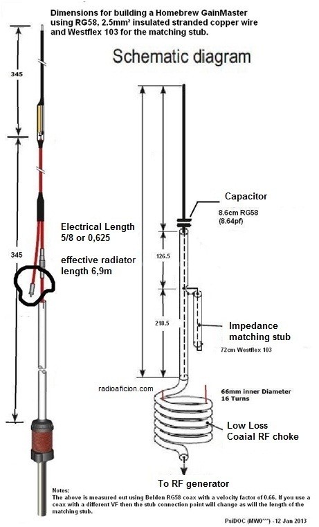
A center fed 5/8 wave vertical covering 26 to 28 MHz, matched using coax for a capacitor and a stub, DC grounded, mechanically and electrically simple, no ground plane needed.

I ran across this interesting antenna design on VK5ST QRZ bio after completing a 10m FT8 contact yesterday.

Gain Master antenna diagram

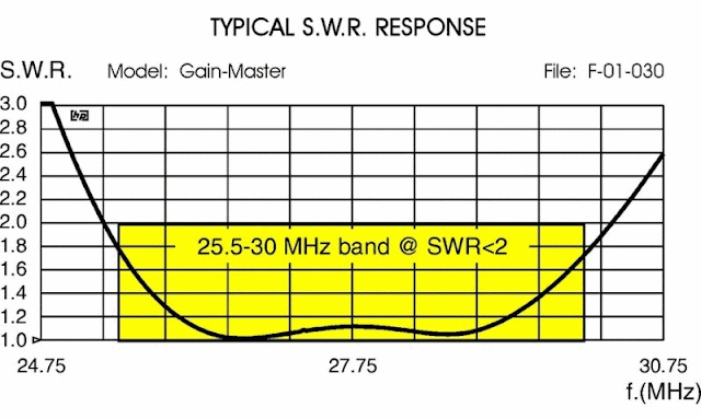
Gain Master SWR plot

Ok, that got me interested, center fed verticals don't get much attention. A while ago I discovered on my own they are pretty good, much better elevation pattern stability compared to end fed over a ground plane, quieter on receive and they perform quite well in my opinion :-)

As with all antenna designs, it's always good to model them to see what we can learn, and what to expect before getting too excited..


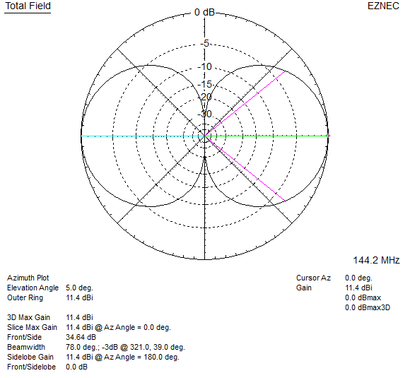
EZNEC Gain Master elevation plot

EZNEC Gain Master SWR plot


When modeled 15ft above average ground it has a shade more gain at 2.6 dBi, maybe half a dB more quickly looking at a conventional 5/8 ground plane model I have.

The SWR response is quite broad, 2 MHz bandwidth at 1.5:1 or better. This would flatten out even more with feed line losses etc. This antenna could easily cover the New Zealand 26 MHz CB band, 27 MHz CB band, and the bottom of 10 meters!

Model: Gain-Master

I had to change the capacitor value to 14 pF which resonated the antenna at 27.3 MHz and provided a very near perfect 50 ohm match leaving the stub length and position as is.

Transmission line 1 is the length between where stub attaches and the capacitor.
Transmission line 2 is the shorted stub length.
V1 where they meet is the 50 ohm feed-point (source).

----------

How does this antenna work?

Specifically the function of the capacitor and stub to match it.

The good thing about antenna modeling, is we can take antennas apart and put them back together again to learn how they work by making a change and looking at the result.

At the center of a split 5/8 wavelength dipole in EZNEC we see 180 + J 420 ohms:
  • Top half is wire extending beyond capacitor, bottom half is the outside of the coax shield down to the choke.
  • Capacitor in series with the center conductor tunes out the inductive reactance leaving 180 ohms resistive.
  • 50 ohm point is found where the stub attaches, the coax from this point running down to the choke is matched to 50 ohms.
  • The length of coax between the end of the stub (hanging off the side) and the capacitor forms the total stub length.
  • Assuming I got my math right: The length of the stub is a 1/4 wavelength at 25 MHz when the VF of 0.66 is taken into account! Why this length I'm not sure, we can shorten the stub to be a 1/4 wave at 27.2 MHz and with some trial and error find the 50 ohm point and a cap value that gives a 50 ohm match.

From there the antenna is simply a center fed vertical dipole made out of coax. The wire beyond the capacitor is the top half, the coax shield down to the choke is the bottom half, the stub hanging off the side would appear to have little to no effect.

An example of a 1/2 wave vertical dipole made of coax and wire is K9YC's Vertical Dipole, except being a 1/2 wave it doesn't need a matching network as its resonant on its own and close enough to 50 ohms. A simple series matching section could make it perfect. It wont have the same broad bandwidth however. Uses ferrite for the choke which is a much better choice especially for high power use.

As for the choke, its size and number of turns isn't close to anything on the chart at http://www.karinya.net/g3txq/chokes/. An analysis would need to be done on the Gain Master choke to better understand it. Since it remains an unknown I would personally use a ferrite choke such as those used by K9YC's vertical dipole as an example. For more about air core chokes see Air Core Coax Chokes: Good, Bad and Ugly by VE3VN.

Getting back to the stub for a moment, using a shorted 1/4 stub I've seen used as a technique to broadband inverted L antennas on 160m - http://mobileers.com/main/wp-content/uploads/2017/01/N9LYE-22L22.pdf (web.archive.org - original is gone). Experimenting with the model as a 5/8 split dipole (source in the center) and the capacitor to get 180 ohms resistive, adding a 1/4 wave stub by it self does have a broad-banding effect, but that is likely a bonus secondary function of the matching stub in the Gain Master design.

----------

I ran the model through AutoEZ to use variables and the optimizer, it made very incremental changes to the values for the capacitor, the stub length and position - basically nothing to be gained, this design is perhaps already quite optimized!

Adding a 1 to 5 meg ohm 5W metal film resistor across the cap to bleed off static buildup also a good idea.

Sunday, November 14, 2021

Doublet Antenna

130 ft Doublet Antenna, covers all nine HF bands 80m - 10m, and optionally 160m with reasonable patterns.

600 ohm feeder > 1:1 ATU balun > switching network > Remote antenna coupler / tuner. 

Doublet antenna remote ATU

The conundrum I had was how to get all nine HF bands 80m - 10m, and 160m from one antenna, with reasonable patterns, performance, and rated for high power. My limitation is having 1/4 acre where I can fit at most 130 ft of wire in a straight line horizontally.

Decided a doublet fed with 600 ohm open line into a remote ATU was the best option. Also, linking the feeders together and driving it against ground as a T antenna enables use on 160m, and a useful set of alternate patterns on 80 through 40m.

The matching network we bring into the 21st century, high quality remote ATU and high quality 1:1 ATU current balun. Remember, any system is only as strong as the weakest link..

  • Balun Designs model 1171 5 kW 1:1 ATU current balun (studs in, studs out).
  • Remote ATU Stockcorner JC-4s 1 kW automatic antenna tuner (5 stars on eHam).
  • Doublet and feeder from TrueLadderLine. Could built it, cheaper to buy it vs time.

The JC-4s ATU can be interfaced to Kenwood and Icom rigs to operate via the Tuner button, and setup to bypass keying an amplifier during tuning. See JC-4s Automatic ATU and Icom IC-7300 Hints on PA0FRI's site.

Initially tuner was very slow to find matches on the upper HF bands when interfaced to the Icom ATU port, but was very quick using the supplied manual tuner interface and 15W carrier to tune. The TUNE carrier power in my Icom 7300 was under 10W, raised it to around 15W the per the service manual which solved the problem.


T Antenna mode, this turns it into a vertical with top loading by feeding the two legs of the feeder together against ground:

  • 160m - 1/8th wave vertical, top loading results in uniform current along the vertical.
  • 80m - 1/4 wave vertical, top loading moves current max to top away from ground noise.
  • 60 to 40m - not sure how you would describe it.
Since the ATU is 10 ft above ground, this places it around 15% up the total vertical length, EZNEC predicts reasonable impedances.

For a while I've been undecided if the T (or an inverted L / vertical monopole) should be directly connected to the ATU's "hot" output terminal, and the ATU ground connected to ground, OR if the 1:1 balun should be left in place, with the T connected to one terminal and ground to the other.

According to W8JI's Counterpoise Systems page the latter should be used, as the overall antenna system is neither perfectly balanced or un-balanced. It is better to force equal and opposite currents, and ensure the coax and control cable shields are choked/isolated so they do not become part of the antenna system. The shields should still be grounded beyond the choke for lightning protection per NEC.

Feeding the system with the balun inline resulted in better matches on 40m, and got rid of an RFI problem.

Sept 2023 I have a remote switching network in the works that will be driven from the JC-4s A/B signal allowing me to remotely change between a doublet and vertical T. More about that once I get it installed.

So, how does it work? I had it up on Oct 21 but connected to my Icom AH-4 tuner which limited me to 100W while I waited for the JC-4s. With the 100 ft feeder strung up to the AH-4 in a temporary location it tuned all bands except 160m.

The first thing I noticed was how much quieter it is on receive compared to my OCFD which had a Balun Designs OCF balun optimized for the job with a good amount of current choking. Now I wonder how much noise is picked up by the coax shield and leaks or couples past the balun to the antenna, then back into the receiver? Noise dropped two to three S units between 80 and 20m.

So far the results on 12, 15, 17, 20, 30m have been good on FT8. SNR each way mostly equal, and looking the TX/RX performance with other stations in my grid on pskreporter things are fairly comparable.

Morning of 22 Oct 21 I worked 8J1RL Antartica on 40m FT8, about 1 hour after sunrise.
Confirmed in LoTW so not making this up :-)


8J1RL FT8 QSO


Later, 7P8RU Lesotho on 17m FT8 (since got them on 12, 30, and 60m), and if that wasn't enough.. After days and days of trying to get 3DA0WW Eswatini using the OCFD and up-to 500W on different bands, I successfully worked them at greyline that evening on 80m FT8 with 80W

That I managed to get those three rare ones with only 80W TX on my end was a nice surprise.

Weekend Oct 30 was CQ WW SSB contest, we had some good propagation on the upper bands. Saturday I worked a number of stations on 10m SSB with 100W in South America, Caribbean, and Japan late in the evening. KL7RA a well known contest station in Alaska commented I had the biggest signal on 15m they'd seen.. Probably something to do with one of those 9.8 dBi lobes that falls north west :-)  also worked them on 20 and 40m. 9/10 times I'd get heard on the first or second call, following morning on 20m got OH8X (super station in Finland), and a couple others.

Also got excellent reports on 75m AM running "bare foot" 25W carrier power.

13 Nov 2021, I now have the JC-4s installed, and feeder length tuned for good matches on all bands, I used my RigExpert to do this so I can be sure that complex impedances the tuner sees are reasonable.

14 Nov 2021, I see Kuwait operating on 20m FT8, watched for a while no decodes. Checked again an hour or so later, decoding up to -6 dB, tried for 10 - 15 minutes with 80W, no luck. Hit it with 400W and completed the contact. I had to pick my self up off the floor when the RR73 appeared. From my location near Seattle, Kuwait is right over the north pole, middle of day here, night there. Unbelievable.

I'm suspiciously optimistic this antenna just seems to work better than all previous wire antennas I have used by a good margin (dipoles, trapped dipoles, OCFD), it keeps surprising me.

Actual readings taken with a RigExpert analyzer connected to the 1:1 ATU balun in doublet mode:

Band

R Ω

X Ω

SWR

10m

162.2

-93.9

4.4

12m

136.3

-114.1

4.8

15m

56.7

-178.6

13

17m

35.7

-163.1

17

20m

52.7

-259.6

28

30m

486.0

151.9

11

40m

102.4

-442.2

41

60m

98.1

109.8

4.7

75m

137.9

-445.6

32

80m

313.5

-659.6

34

160m

12.0

-141.9

38

This is with the antenna at a height of about 55 ft or 17 m, and approx 70 ft or 21 m of 600 ohm open wire line.

This shows me that the ATU has quite reasonable complex impedances to match, or no wild extremes at least.

R is a little low on 160m but at 130 ft or 40 m long the doublet is well too short at 1/4 wave length, but it does work no doubt with reduced efficiency. In T mode on 160m it would work much better as a DX antenna on transmit at least..

This also highlights the trap of assuming a 4:1 balun should be used, in nearly all cases this would lower the impedance too much. See Tuner Balun 4:1 or 1:1 for more about that.


Introducing the "All Band" Doublet - Cebik.

10 Frequency Asked Questions about the All-Band Doublet - Cebik.

Tuner Balun: 4:1 or 1:1? - G3TXQ.

80-Meter Doublet - KV5R.


Sunday, July 11, 2021

STREB VHF Compact Beam Revisited

The STREB VHF Compact Beam by Bert Looser ZL4IV is a 2m antenna which appeared in October 1992 BREAK-IN, the official amateur radio journal published by NZART (New Zealand Association of Radio Transmitters).

Article Page 1 and Page 2.


EZNEC STREB antenna view

A local ham and good friend Bill ZL1DEF (SK) gave me the temporary one he built to play around with sometime in 1994. The day I tried it out must have had some enhanced propagation as I could access a 2m repeater that was usually just out of reach with out help from a band lift. I thought wow, this antenna has the secret sauce I need!

I took it down and planned to build a weather proof version. That never happened and another friend of mine at the time commented probably a band lift, which I would later confirm since an 8 element NBS Yagi and 100W couldn't access or hear that repeater under normal conditions.

But this unique antenna never quite left my mind, getting back into ham radio around 2007 after a 10 year break the topic of this antenna came up while chatting on a local repeater and I was able to obtain copies of the two pages above.

Another 14 years later and having learned to model antennas over the last couple of years I decided it was time to model the STREB and take a closer look.

I created a model per the dimensions and tube thickness used in the article (6.4 mm or 1/4 inch) in EZNEC, the front to back ratio was low at around 10 dB, and resonance was well below the 2m band. Not sure why the discrepancy.

I contemplated trying to optimize it by hand, I've done this in the past with other antenna designs but the motivation didn't appear, so I decided to gain some experience with the the AutoEZ optimizer and put it to to work..

Well, blow my socks off! AutoEZ optimizer vastly improved the front to back, 20 dB or better across the 2m band, and moved the resonance to 146 MHz. The feed-point impedance came out around 135 ohms, using a section of 75 ohm coax to transform the impedance and wound on a toroid to also form a choke would bring that to 50 ohms with the SWR rising past 1.5:1 at the band edges according to EZNEC.

One change I made was aligning the two parasitic elements in the same plane in both models with a 50 mm spacing, the article has them either side of the RF cage (more or less a 1/2 wave dipole bent into a square fed at one corner), this didn't seem to do anything useful other than offset the pattern from the plane of the antenna.

See 2m-STREB for model files etc.

Article figure 5 measurements after AutoEZ optimization:

A =  959 mm (Director/front element)
B = 1013 mm (Reflector/rear element)
C =   62 mm (Gap between open ends of RF cage)
D =  270 mm (Height) x 209 mm (Length) (RF cage top half)
E =  271 mm (Length) x 270 mm (Height) (RF cage bottom half)


EZNEC STREB azimuth plot
Original vs optimized azimuth patterns in free space.


EZNEC STREB azimuth plot
Optimized azimuth patterns at 144, 146, and 148 MHz in free space.


EZNEC STREB elevation plot
Optimized elevation pattern 5 meters above real ground, vertical polarization


You might think, that's a mildly complicated antenna in an effort to reduce the size (but still poke your eye out with), and doesn't have a direct 50 ohm feed. What else is there? A Moxon rectangle has a similar size reduction, is simpler to build, direct 50 ohm feed, and are a well known tried and true design at this time. Interestingly both the STREB and Moxon appeared at about the same time.

Sunday, April 11, 2021

2m Horizontal Dipole Stack

Simple horizontally polarized antenna for 2m SSB. Two dipole stack 11 dBi at 5 degrees elevation (at 6m height). Build it in an afternoon..

Since I have an Icom IC-7100 in the shack which covers 2m and 70cm all modes, why not have a horizontally polarized antenna for some 2m SSB action? Most have Yagi's but with those comes the need for a rotator etc. This I built in an afternoon to try out with scrap items or stuff easily found at a hardware store - 75 ohm coax, some wire, screws, PCV tube etc.

An EZNEC model shows a horizontal dipole 6m / 20 ft above ground to have around 8 dBi gain with a bi-directional beam-width of 80 degrees, but it has a number of nearly equally strong high angle lobes which is a waste of energy going nowhere useful, and would also lower the SNR of desired signals.

I found stacking a second dipole 1m (1/2 wave length) above boosted the gain to 11.3 dBi and significantly reduced the overhead lobes. Feeding each dipole half way between with 75 ohm coax (0.5m each) resulted in a 44.4 J0 ohms match or an SWR of 1.12:1 where they meet in the middle, close enough for 50 ohm coax.

(not to scale)

EZNEC 2m 2 dipole stack elevation plot
Two dipole stack 6m / 20ft height above ground elevation plot


EZNEC 2m 2 dipole stack vs diple elevation plot
Two dipole stack 6m / 20ft height compared to a single dipole same height


EZNEC 2m 2 dipole stack azimuth plot
Two dipole stack azimuth plot


Model file: 2m 2 Dipole Stack.

I built this antenna in a couple of hours using some scrap PVC tube for the vertical mast, copper wire out of scrap Romex cable, scrap 75 ohm RG-6, and some sheet metal screws and washers. I also put a pair of snap on ferrites at the feed-point of each dipole, and also over the 50 ohm line leading away at the lower dipole.

2m 2 dipole stack test antenna photo

Seems to work alright, SWR meter in the IC-7100 reads 1:1 at the bottom of the 2m band, and rises slightly at the top/148 MHz.

On 440 MHz SWR around 1.6:1 works ok with the local FM repeaters.

Had a QSO with another station 20 miles away on 144.200, S9 each way. On the Comet GP-15 vertical which is a 2 x 5/8 on 2m they were S2.

Monday, March 22, 2021

40 ft Vertical Doublet 40m - 10m

Vertical doublet / dipole - on 10m an EDZ (2x 5/8) with 4.5 dBi gain, 30m its just under a 1/2 wave dipole, and 40m a little on the short side but will work ok.

Started off with the idea of building an elevated vertical with radials to cover the upper HF bands, using an Icom AH-4 ATU at the feed-point to match it.

A 5/8 wave vertical for 10m is around 20 ft long, a 1/4 wave on 30m is around .. 23 ft. This would cover the upper HF bands. I like to model antennas before I build them for the experience and to get an idea of what to expect.

Modeling an elevated vertical trying different length radials didn't look so good, high angle lobes would form on some bands and the gain was mediocre at best. Running radials everywhere was not entirely convenient either.

I searched around for other possibilities, ZS6AAA designed a Compact Quad Multi Band HF Antenna which fits on a 40 ft Spiderbeam fiberglass pole that covers 40m through 10m. In my case easier said than done, needs to be guyed at several points.

Back to verticals, I thought delete the radials and center feed it? How long can I make it before the lobes go silly on 10m - the highest band? 40 ft. I was quite amazed at what I had discovered - only to find it was in-fact nothing new. However..

On 10m it's a vertical EDZ (Extended Double Zepp) or a 2 x 5/8 with 4.5 dBi gain at 10 degrees, and on 30 m it's just shy of a 1/2 wave dipole and 0.82 dBi with lowest point 10 ft above average ground.

40 ft vertical doublet AH-4 diagram

40 ft vertical doublet elevation plot

40 ft vertical doublet elevation plot

These patterns are much nicer than an elevated 1/4 or 5/8 wave ground plane antennas.


I have a 40ft Spiderbeam pole which I mounted on the 2nd level rear deck placing the bottom 10ft above ground. A surplus ZS6BKW I shortened the legs down to 20ft and keept the 40ft 450 ohm window line section as is, window line leads away at around 45 degree angle across to a roof eave where I mounted a short piece of PVC pipe with small section removed for the window line to fit over and rest on keeping it above the roof.

The first version (based on https://www.hamoperator.com/HF/AH-4_Design_and_Operation.pdf) I had the window line split between the output and ground terminal of the AH-4 tuner. CM chokes are placed on the coax and control cable. I used 3/4" mix 31 snap ons with enough turns of cable for a snug fit.

I later found using a 1:1 ATU balun between the AH-4 and balanced line worked a lot better. The AH-4 got better matches, and an RFI problem on 17m went away. The ATU balun was from Balun Designs. The CM chokes on the coax and control cable are still a good idea and were left in place in as well.

Made a 50ft control cable extension using quality CAT5e joining the pairs to make a 4 wire cable. I put a CAT5e tail with the RJ-45 left on (cut a patch cable in half) the tuner end and the end of the supplied control cable, lets me change the length by using CAT5 couplers and different length cable in-between.

I put a 3 Meg Ω 5W metal film resistor across the window line to bleed off static charge buildup via ground lug which is common to the coax shield in the tuner, coax shield is grounded where feed lines enter the house - make sure you meet NEC / electrical code (Grounding and Bonding - ARRL is a good book for North America and in general / and where applicable - consult professionals as needed).


AH-4 photo40 ft vertical doublet photo


Pictures, taken before I added the 1:1 balun.

The AH-4 tunes all bands 80m to 6m no problem, but I would question the efficiency of this system below 40m.

Comparing it with my 80m OCFD at 55ft from my location near Seattle WA, the vertical does surprisingly well.

SSB: On 40m the OCFD is always better which is expected. On 20m and up the OCFD will pull out the weak signals a little better. Local nets on 10m where the vertical up-to 9 S-units better in some cases, I'm assuming others are using verticals on 10m.

On 6m the vertical has high angle lobes but works ok on local 6m FM repeaters, for better performance we could add 6m traps 5/8 wavelength (on 6m) down each leg which would make it a vertical EDZ on this band. Keeping in mind to account for the loading the traps add on HF, it may need to be shortened a little to keep 10m in check.

FT8: Running two instances of WSJT-X with two radios (IC-7100 on vertical, IC-7300 on OCFD) with one reporting my callsign with /P to make it easy to tell them apart on pskreporter and watching FT8 signals on 20m through 15m the OCFD hears around 20% more stations. There are a few cases both on SSB and FT8 where the vertical does better, likely in directions where the OCFD has a null. I should probably repeat the tests with the antennas swapped to see how much of that 20% is attributed to the IC-7300's SDR receiver..

Horizontal antennas 1/2 wavelength or more high are hard to beat due to the gain from ground reflections, this vertical is a close 2nd to the OCFD on the upper bands.

A permanent install would need to by guyed (using non conductive line) at the feed point with the window line supported / suspended from one - when the wind catches the window line things things start swinging and wobbling around more than I'd like.

Overall I'm quite pleased with this vertical, it's simple, light weight, no radials, and the results have surprised. Down sides are you need a good remote tuner, and a means to lead the window line away at 45 degree angle or higher if possible. In my case neither of these were an issue.

I can now also see why feeding balanced antennas with 450 ohm line to a good tuner is popular, it works well! Personally I've had little experience with this way of doing things.

A shorter version could also be used covering 17m to 6m, at 24 ft, it would be an EDZ on 6m, and just under 1/2 wave on 17m.

Related info:


Tuesday, January 5, 2021

Receive Antenna RDF Metric

Receiving Directivity Factor (RDF) helps determine the performance of antennas on receive, this is useful with lower HF bands under 10 MHz where noise becomes an increasing problem. RDF is the difference between the peak forward gain and averaged gain in all directions.

RDF value can be calculated using an EZNEC model:

  • Set plot type to 3D, click FF Plot, average gain displayed at the bottom of EZNEC window.
  • In the 3D Plot window click View > Show 2D Plot, the peak forward gain is displayed.
  • Subtract peak gain from average gain, this is the RDF figure.

Here's an example using a LoG (Loop on Ground) phased array I modeled:

EZNEC antenna RDF metric
Click for lager image

Average gain -37.06 dB minus peak gain -28 dBi = RDF of 9.06 dB, which in the world of RDF and receive antennas is respectable.

Reason I post this, is it's easy to find pages discussing RDF and figures of various antennas, but only two places I found mention how to calculate it - Receiving Basics and The Challenge: Receiving Antennas.

More about The RDF Metric.


More can be found by searching for Antenna RDF or Receiving Directivity Factor.

Thursday, December 24, 2020

Phased Arrays - 40m Verticals no Radials

40m phased vertical array using a pair of verticals based on W6NBC's design from http://www.w6nbc.com/articles/2014-QST40mvertical.pdf. These are essentially a vertical dipole with loading in the bottom leg at the feed-point. In the model I created the total height is around 50ft with the bottom end 5ft above ground level. Not needing radials makes this an attractive design if the space available isn't suitable for radials. 

Phasing a pair of them spaced 1/4 wavelength apart using OVF results in good performance with 3.2 dBi gain at 22.5 degrees elevation with over 20 dB F/B, and 10 dB F/B at 7.0 and 7.2 MHz. Matched SWR is 1.5:1 at the edges. I had tried closer spacings but the F/B and SWR bandwidth is significantly narrower

Opposite Voltage Fed (OVF) arrays were developed by Pekka Ketonen OH1TV. His site contains several examples in different configurations, including details on direction switching and matching networks. OVF uses 1/2 wavelength lines, at a common point where they meet a loading inductor is put in series with one line which makes the array directional, and with a relay electrically reversible. An L match network matches to 50 ohms. The system is simple and can offer much broader F/B and SWR performance compared to coax delay lines or current forcing.

A previous post Phased Arrays - Opposite Voltage Fed (OVF) using a pair of elevated 1/4 wave verticals attempts to explain how the transmission lines, loading and matching networks are "wired up" in the model with virtual connections.

Model file W6NBC_40m_Vert_2El_OVF.ez.

Plots:


What's often remarkable about OVF is how well the F/B and pattern is controlled either side of the design frequency.

In the model the first L network is the loading inductor for the "rear" element - no shunt is needed so a 1M ohm resistor represents an open circuit.

The direction of the array is switched by changing which side of the loading inductor is fed. The OVF array articles on OH1TV's site show examples. To reverse the direction in the model change V1 to V2 in the second L network. The second L network is for matching, by chance it only needs a 200 pF shunt.

Current chokes are needed where the feed-lines connect to each element in the array, and the polarity is reversed on one of the 1/2 wave lines.

Other phasing systems? Calculating coax delay lines resulted in line lengths too short to reach a common point to enable direction switching. A model using current forcing works but the F/B and pattern shape degrade quicker either side of the design frequency. An example of the difference between current forcing and OVF is shown in Phased Arrays - 40m Twin Half Square.

The Phased Arrays link at the bottom will show other examples using different systems and antenna types, and how they can compare.

Incidentally it was the idea and a QRZ post about phasing a pair of these verticals several months ago that got me started on the path to modeling and better understanding phased arrays and how the different feed systems work.

-----

Models are good starting point, and a way to investigate and better understand antenna systems. These tools can also help guide us to and validate the final result, if a good correlation is observed in the real world then we can have confidence the patterns and other information are accurate.

The models I have created and made available may contain errors, or overlook something someone more experienced can see. I don't claim to be an expert or authority on the subject of antenna modeling or phased arrays. I simply want to further my own knowledge and understanding of antennas which I find fascinating. Comments, suggestions, discussion are welcome - lonney@gmail.com.

This post is one of several on Phased Arrays.