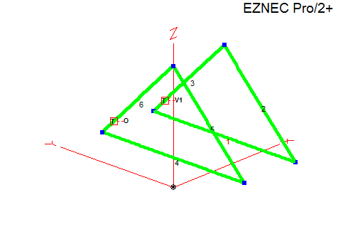
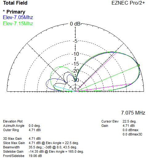
Parasitic (driver + reflector), reversible, direct 50 ohm feed, equal length 75 ohm sections for matching and the open stub long enough to reach a common switching point.
Recently during the middle of the day I noticed a local station here on the US west coast spotting EU stations on 40m FT8 via psk reporter. This is fairly unusual due to day time D layer absorption, but not impossible. I emailed asking for more info about the antenna they were using, they replied saying they had built a two element delta loop array based on 40 Meter Parasitic Delta Loop Array by W8WWV.
Trying to model this by hand in EZNEC the results were not great, especially trying to get a 50 ohm match. Since there are interactions with element spacing, resonance, etc - change one thing it throws off several others.
Decided to give this problem to the optimizer in AutoEZ. Optimizing for gain and direct 50 ohm feed, I let the optimizer adjust the length of the bottom wire, the height of both loops, and the feed positions symmetrically, and vary two equal lengths of 75 ohm coax for the open stub and matching section to keep it simple.
I was pleasantly surprised when AutoEZ found a perfect solution using two equal length sections of 75 ohm coax that will easily reach a common point, and provide a direct 50 ohm feed!
Searching around for information on designs using switched open stubs, there are a few which use 3/8 λ open stub for the reflector.
Interesting to note, the starting model I had used equilateral triangles (what I happened to have), the optimizer settled on right angle triangles (very close at 89 degrees). Agrees with accepted wisdom for vertically polarized deltas, see SCV Polarized Wire Antennas: The Delta Branch - L.B. Cebik.
On to the details..
Item | Measurement |
Horizontal wire height above ground | 3 m / 9.8 ft |
Horizontal wire length | 18.28 m / 60 ft |
Height to apex above ground | 12.31 m / 40.3 ft |
Side wire length | 13.04 m / 42.78 ft |
Element spacing | 7 m / 23 ft |
Feed position up side | 16.3% or 2 m / 6.5 ft |
75 Ω coax length from each element | 13.74 m / 45 ft (VF=1) |
Each 75 ohm line meets at a common point:
- 75 ohm line connected to the driver matches the system to 50 ohms.
- 75 ohm line to the other element is left open circuit resonating it as a reflector.
- Direction reversed by swapping which is open and which is connected to the driven element.
With the 75 ohm lines being equal lengths and one is open circuit, the switching network/relay wiring is kept simple.
Current chokes at each loop feed-point: With the VF of the coax used measured and taken into account, there should be enough excess length to use for a current choke (winding it around ferrite) at each loop feed-point (the choke must preserve the line impedance and electrical length), and to reach a common point for switching.
The model uses bare 12 AWG copper wire, and VF of 1 for the 75 ohm coax. The model would need to be updated if using insulated wire and re-optimized, the VF of the coax being used would need to be measured with an analyzer and length multiplied by that number (e.g. 0.8 or what ever it is) to get the electrical length.
As a test when I updated the model using RG-11 factoring in VF and loss figures, there is a small 0.3 dB or so drop in gain, this will be partly from the SWR on the matching section and the effect of the open stub causing small losses.
Now if only I had the room to build it :-)
EZNEC and AutoEZ model files: 40m 2 Element Delta Loop.
Dec 2024, I ran across The Parasitical Right-Angle Delta towards the bottom of https://antenna2.github.io/cebik/content/wire/hsyg.html, simpler system using shorted stubs with 75 ohm coax, and 50 ohm feed.


