Sunday, July 11, 2021

STREB VHF Compact Beam Revisited

The STREB VHF Compact Beam by Bert Looser ZL4IV is a 2m antenna which appeared in October 1992 BREAK-IN, the official amateur radio journal published by NZART (New Zealand Association of Radio Transmitters).

Article Page 1 and Page 2.


EZNEC STREB antenna view

A local ham and good friend Bill ZL1DEF (SK) gave me the temporary one he built to play around with sometime in 1994. The day I tried it out must have had some enhanced propagation as I could access a 2m repeater that was usually just out of reach with out help from a band lift. I thought wow, this antenna has the secret sauce I need!

I took it down and planned to build a weather proof version. That never happened and another friend of mine at the time commented probably a band lift, which I would later confirm since an 8 element NBS Yagi and 100W couldn't access or hear that repeater under normal conditions.

But this unique antenna never quite left my mind, getting back into ham radio around 2007 after a 10 year break the topic of this antenna came up while chatting on a local repeater and I was able to obtain copies of the two pages above.

Another 14 years later and having learned to model antennas over the last couple of years I decided it was time to model the STREB and take a closer look.

I created a model per the dimensions and tube thickness used in the article (6.4 mm or 1/4 inch) in EZNEC, the front to back ratio was low at around 10 dB, and resonance was well below the 2m band. Not sure why the discrepancy.

I contemplated trying to optimize it by hand, I've done this in the past with other antenna designs but the motivation didn't appear, so I decided to gain some experience with the the AutoEZ optimizer and put it to to work..

Well, blow my socks off! AutoEZ optimizer vastly improved the front to back, 20 dB or better across the 2m band, and moved the resonance to 146 MHz. The feed-point impedance came out around 135 ohms, using a section of 75 ohm coax to transform the impedance and wound on a toroid to also form a choke would bring that to 50 ohms with the SWR rising past 1.5:1 at the band edges according to EZNEC.

One change I made was aligning the two parasitic elements in the same plane in both models with a 50 mm spacing, the article has them either side of the RF cage (more or less a 1/2 wave dipole bent into a square fed at one corner), this didn't seem to do anything useful other than offset the pattern from the plane of the antenna.

See 2m-STREB for model files etc.

Article figure 5 measurements after AutoEZ optimization:

A =  959 mm (Director/front element)
B = 1013 mm (Reflector/rear element)
C =   62 mm (Gap between open ends of RF cage)
D =  270 mm (Height) x 209 mm (Length) (RF cage top half)
E =  271 mm (Length) x 270 mm (Height) (RF cage bottom half)


EZNEC STREB azimuth plot
Original vs optimized azimuth patterns in free space.


EZNEC STREB azimuth plot
Optimized azimuth patterns at 144, 146, and 148 MHz in free space.


EZNEC STREB elevation plot
Optimized elevation pattern 5 meters above real ground, vertical polarization


You might think, that's a mildly complicated antenna in an effort to reduce the size (but still poke your eye out with), and doesn't have a direct 50 ohm feed. What else is there? A Moxon rectangle has a similar size reduction, is simpler to build, direct 50 ohm feed, and are a well known tried and true design at this time. Interestingly both the STREB and Moxon appeared at about the same time.

Tuesday, May 25, 2021

First QSL Card

Well not quite, in the 90s I collected a large number of QSL cards from the CB radio days which I no longer have, I suspect I threw them out which I regret..

Yet somehow after near 30 years of being a ham I've never received a QSL card (or sent one)!

That changed recently when I heard special event station W5L on 20m SSB one afternoon commemorating the 218th anniversary of the Louisiana purchase.

I tried for a while to get through the pileup of other stations calling with my vertical doublet and 100W but had no luck, so I gave up and went back outside for a couple hours. Came back to the shack and W5L was still there calling for stations, and getting few responses so I gave a call and made the contact.

The QSL card I got back is a very nicely done folded card:

W5L QSL card
Front

W5L QSL card
Back


W5L QSL card
Inside half


Sunday, April 11, 2021

2m Horizontal Dipole Stack

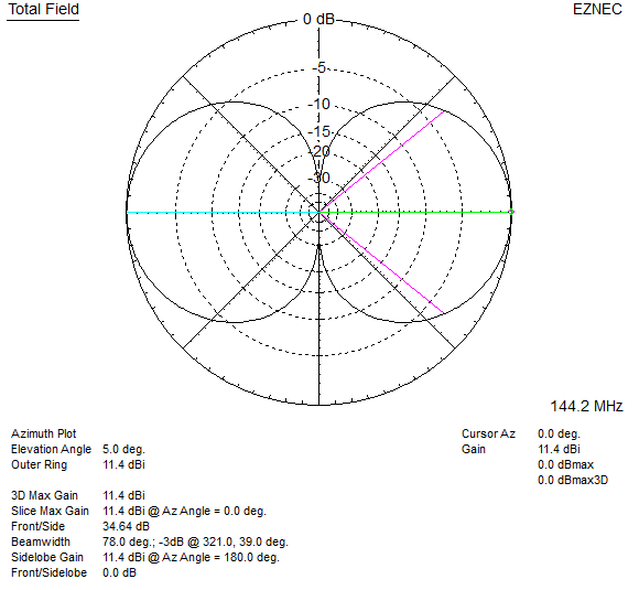
Simple horizontally polarized antenna for 2m SSB. Two dipole stack 11 dBi at 5 degrees elevation (at 6m height). Build it in an afternoon..

Since I have an Icom IC-7100 in the shack which covers 2m and 70cm all modes, why not have a horizontally polarized antenna for some 2m SSB action? Most have Yagi's but with those comes the need for a rotator etc. This I built in an afternoon to try out with scrap items or stuff easily found at a hardware store - 75 ohm coax, some wire, screws, PCV tube etc.

An EZNEC model shows a horizontal dipole 6m / 20 ft above ground to have around 8 dBi gain with a bi-directional beam-width of 80 degrees, but it has a number of nearly equally strong high angle lobes which is a waste of energy going nowhere useful, and would also lower the SNR of desired signals.

I found stacking a second dipole 1m (1/2 wave length) above boosted the gain to 11.3 dBi and significantly reduced the overhead lobes. Feeding each dipole half way between with 75 ohm coax (0.5m each) resulted in a 44.4 J0 ohms match or an SWR of 1.12:1 where they meet in the middle, close enough for 50 ohm coax.

(not to scale)

EZNEC 2m 2 dipole stack elevation plot
Two dipole stack 6m / 20ft height above ground elevation plot


EZNEC 2m 2 dipole stack vs diple elevation plot
Two dipole stack 6m / 20ft height compared to a single dipole same height


EZNEC 2m 2 dipole stack azimuth plot
Two dipole stack azimuth plot


Model file: 2m 2 Dipole Stack.

I built this antenna in a couple of hours using some scrap PVC tube for the vertical mast, copper wire out of scrap Romex cable, scrap 75 ohm RG-6, and some sheet metal screws and washers. I also put a pair of snap on ferrites at the feed-point of each dipole, and also over the 50 ohm line leading away at the lower dipole.

2m 2 dipole stack test antenna photo

Seems to work alright, SWR meter in the IC-7100 reads 1:1 at the bottom of the 2m band, and rises slightly at the top/148 MHz.

On 440 MHz SWR around 1.6:1 works ok with the local FM repeaters.

Had a QSO with another station 20 miles away on 144.200, S9 each way. On the Comet GP-15 vertical which is a 2 x 5/8 on 2m they were S2.

Tuesday, April 6, 2021

Trying out FT8..

I got around to trying out FT8, the HF digital mode that everyone seems to be doing these days. I guess don't knock it until you try it..

It makes completing a contact very easy after setting some options.

Answering a CQ just double click station calling CQ, from there the process of your station answering, the exchange of callsigns, grid square and signal report are fully automated.

Calling CQ is simply clicking enable TX and waiting for others to answer, the same automated process takes over and completes the contact.

I can see this has it's uses with contesting, working a DX-Pedition under trying conditions to get that rare one for example since its simple, automated and completes a contact in five 15 second T/R sequences.

WSJT-X FT8 QSO

Here on the 17m band yesterday evening completed my very first ever FT8 contact with ZL2DD.

Monday, March 22, 2021

40 ft Vertical Doublet 40m - 10m

Vertical doublet / dipole - on 10m an EDZ (2x 5/8) with 4.5 dBi gain, 30m its just under a 1/2 wave dipole, and 40m a little on the short side but will work ok.

Started off with the idea of building an elevated vertical with radials to cover the upper HF bands, using an Icom AH-4 ATU at the feed-point to match it.

A 5/8 wave vertical for 10m is around 20 ft long, a 1/4 wave on 30m is around .. 23 ft. This would cover the upper HF bands. I like to model antennas before I build them for the experience and to get an idea of what to expect.

Modeling an elevated vertical trying different length radials didn't look so good, high angle lobes would form on some bands and the gain was mediocre at best. Running radials everywhere was not entirely convenient either.

I searched around for other possibilities, ZS6AAA designed a Compact Quad Multi Band HF Antenna which fits on a 40 ft Spiderbeam fiberglass pole that covers 40m through 10m. In my case easier said than done, needs to be guyed at several points.

Back to verticals, I thought delete the radials and center feed it? How long can I make it before the lobes go silly on 10m - the highest band? 40 ft. I was quite amazed at what I had discovered - only to find it was in-fact nothing new. However..

On 10m it's a vertical EDZ (Extended Double Zepp) or a 2 x 5/8 with 4.5 dBi gain at 10 degrees, and on 30 m it's just shy of a 1/2 wave dipole and 0.82 dBi with lowest point 10 ft above average ground.

40 ft vertical doublet AH-4 diagram

40 ft vertical doublet elevation plot

40 ft vertical doublet elevation plot

These patterns are much nicer than an elevated 1/4 or 5/8 wave ground plane antennas.


I have a 40ft Spiderbeam pole which I mounted on the 2nd level rear deck placing the bottom 10ft above ground. A surplus ZS6BKW I shortened the legs down to 20ft and keept the 40ft 450 ohm window line section as is, window line leads away at around 45 degree angle across to a roof eave where I mounted a short piece of PVC pipe with small section removed for the window line to fit over and rest on keeping it above the roof.

The first version (based on https://www.hamoperator.com/HF/AH-4_Design_and_Operation.pdf) I had the window line split between the output and ground terminal of the AH-4 tuner. CM chokes are placed on the coax and control cable. I used 3/4" mix 31 snap ons with enough turns of cable for a snug fit.

I later found using a 1:1 ATU balun between the AH-4 and balanced line worked a lot better. The AH-4 got better matches, and an RFI problem on 17m went away. The ATU balun was from Balun Designs. The CM chokes on the coax and control cable are still a good idea and were left in place in as well.

Made a 50ft control cable extension using quality CAT5e joining the pairs to make a 4 wire cable. I put a CAT5e tail with the RJ-45 left on (cut a patch cable in half) the tuner end and the end of the supplied control cable, lets me change the length by using CAT5 couplers and different length cable in-between.

I put a 3 Meg Ω 5W metal film resistor across the window line to bleed off static charge buildup via ground lug which is common to the coax shield in the tuner, coax shield is grounded where feed lines enter the house - make sure you meet NEC / electrical code (Grounding and Bonding - ARRL is a good book for North America and in general / and where applicable - consult professionals as needed).


AH-4 photo40 ft vertical doublet photo


Pictures, taken before I added the 1:1 balun.

The AH-4 tunes all bands 80m to 6m no problem, but I would question the efficiency of this system below 40m.

Comparing it with my 80m OCFD at 55ft from my location near Seattle WA, the vertical does surprisingly well.

SSB: On 40m the OCFD is always better which is expected. On 20m and up the OCFD will pull out the weak signals a little better. Local nets on 10m where the vertical up-to 9 S-units better in some cases, I'm assuming others are using verticals on 10m.

On 6m the vertical has high angle lobes but works ok on local 6m FM repeaters, for better performance we could add 6m traps 5/8 wavelength (on 6m) down each leg which would make it a vertical EDZ on this band. Keeping in mind to account for the loading the traps add on HF, it may need to be shortened a little to keep 10m in check.

FT8: Running two instances of WSJT-X with two radios (IC-7100 on vertical, IC-7300 on OCFD) with one reporting my callsign with /P to make it easy to tell them apart on pskreporter and watching FT8 signals on 20m through 15m the OCFD hears around 20% more stations. There are a few cases both on SSB and FT8 where the vertical does better, likely in directions where the OCFD has a null. I should probably repeat the tests with the antennas swapped to see how much of that 20% is attributed to the IC-7300's SDR receiver..

Horizontal antennas 1/2 wavelength or more high are hard to beat due to the gain from ground reflections, this vertical is a close 2nd to the OCFD on the upper bands.

A permanent install would need to by guyed (using non conductive line) at the feed point with the window line supported / suspended from one - when the wind catches the window line things things start swinging and wobbling around more than I'd like.

Overall I'm quite pleased with this vertical, it's simple, light weight, no radials, and the results have surprised. Down sides are you need a good remote tuner, and a means to lead the window line away at 45 degree angle or higher if possible. In my case neither of these were an issue.

I can now also see why feeding balanced antennas with 450 ohm line to a good tuner is popular, it works well! Personally I've had little experience with this way of doing things.

A shorter version could also be used covering 17m to 6m, at 24 ft, it would be an EDZ on 6m, and just under 1/2 wave on 17m.

Related info: