Christman Feed System: How to calculate it, and current forcing with examples below.
The best that I can understand it :-)
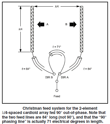
The Christman feed system is well known as using a pair of 84 and one 71 degree line connected together to achieve a 90 degree phase shift with a pair of 1/4 wave ground mounted verticals spaced 1/4 wavelength apart. This produces a directional pattern with a good F/B ratio.
This is a popular choice since it's easy to cut some coax and connect it up!
VA7ST has a handy Christman phasing calculator that will output the cable lengths for a given frequency.
Does it just work with other array types?
No, but that doesn't stop some from wanting it to work :-)
The coax lengths must be specifically calculated to deliver equal current magnitudes (with two element arrays) and the right phase shift based on the drive impedance of each element in the array. If these two requirements are not met, then the front to back (F/B) falls and the performance suffers.
How are these coax delay line lengths calculated?
- Self impedance - impedance of one element by it self is measured.
- Coupled impedance - second element is added, impedance at one element is measured.
- Drive impedances (of each element) - calculations are done with self and coupled impedances in-conjunction with the desired current magnitude and phase shift.
- Once the drive impedances are known, the coax delay line lengths, or L-Network values for use with 1/4 wave lines (Current Forcing), or 1/2 wave lines (Opposite Voltage Fed) can be calculated - OVF info and links at bottom of page.
The calculations are complex, fortunately there are tools to help do these calculations.
The spreadsheet Drive2EL will calculate the drive impedances from the self and coupled impedances, and phase shift. Since it only uses formulas it should also work in other spreadsheet applications such as Libre Office Calc (free). Drive2EL uses (with permission) parts of the formulas from ON4UN's Low Band DXing 5th Ed Excel spreadsheet "w1mk-on4un-oh1tv-arrays.xls" (which can calculate multi-element arrays), and provides a simplified interface for two element array calculations to make it easier.
The spreadsheet Feed2EL will calculate the coax delay line lengths or current forcing L network values, it also includes series and L network matching calculators, and a library of coax cable types. However it requires Microsoft Excel to run the macros it uses.
With out Excel, an alternative would be to use the Windows app Arrayfeed1 (PDF of manual) which only does the coax delay line length and current forcing L network calculations, other calculators would need be used for the series or L network matching - these can be found online.
Practical Examples
Jump to Christman, Current Forcing, Opposite Voltage Fed.
How to work through this calculation process using EZNEC models to measure the self and coupled impedances, and the two spreadsheets to crunch the numbers.
This demonstrates the process one would use when building an array. A two source EZNEC model can also be used to see the calculated drive impedances directly which speeds up the modeling process by eliminating the steps with Drive2EL, this is noted in each example.
When simply experimenting with models using transmission lines I set the VF to 1 and omit the loss figures to keep things simple, then in the final iteration I might add those details in to see the effects.
In these examples for completeness I included the coax VF and loss figures in the models from the library included with Feed2EL. Any final designs which would then be built should include as much accurate detail as possible in the model.
The VF of the coax being used when building feed systems should be measured with an analyzer as the mfg spec is approximate and can vary, it can even vary by frequency! See TLDeails figure 3.
EZNEC models assume various ideals (it is a simulation after all and the outputs are only as accurate as the inputs), the transmission lines for example are virtual and will never carry common mode currents.
In practice 1:1 current chokes/baluns should be used at the feed point of each antenna to ensure equal and opposite currents are forced into the antenna and common mode currents are blocked. The choke also needs to preserve total line length and impedance! My Antennas / Baluns / Feedlines page has links to information on current chokes.
Here are two examples, one using Simplest (coax delay lines) with 40m elevated verticals, and another using L Network (current forcing) with 20m horizontal dipoles.
These examples are just that, examples. They may not result in the best properties or performance possible, the goal here is to show the process as a set of steps.
Note: The voltages, currents, and magnitudes etc displayed by EZNEC are with the power level set to 1000 watts in EZNEC > Options > Power Level. Options > Save As Default will store this change.
Christman (Coax Delay Lines) with 40m Elevated Verticals
This uses 50 ohm coax for the delay lines, and a 75 ohm coax section to match the system to 50 ohms.
The vertical used as staring point is elevated 3 meters / 9 ft above average ground, and has 3 evenly spaced radials created using the Create > Radials function based on wire 3 which calculates the geometry to get the angle and lengths right.
Note: As with the second example below using horizontal dipoles on 20m (which I did first when writing this), I found the array may perform better when it is tuned to resonance when coupling with the second element in position but not connected. In this example I have accounted for that, the coupled reading will show as resonant (no reactance), the self impedance reading will show the antenna resonant above the design frequency. Is this a rule of thumb with coax lines or current forcing? I'm not sure, but it's something I noticed.
Open the Drive2EL spreadsheet.
Open 40m-1-GP.ez.
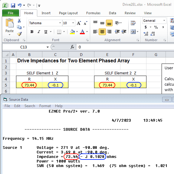
Click Src Dat to see the source data self impedance, and enter these values into Drive2EL both Self Element 1 Z and Self Element 2 Z.
Note: When building an array in practice each antenna on its own may have a different self impedance, so each should be measured separately.
The next two steps are copying and rotating wires, 40m-2-GP-1-Wires.ez has this done.
Add the 2nd element in the array using the copy wires command, offset X by 10.75, and uncheck Copy sources, loads, TL stubs.
Rotate wires 6 through 10 to get the 2nd vertical correctly orientated.
View Ant should look like this (dual 3 radial layout is borrowed from this OVF array by OH1TV):
Click Src Dat to see the source data coupled impedance, and copy the values into Coupled Element Z.
In Drive2EL Element 2 I and Phase change phase to -90, leave Element 1 I and Phase as 1 and 0.
The drive impedances for each element are now displayed.
EZNEC Drive Impedances
-----
Note: If simply experimenting with models we can skip to this step and use a two source model to see the drive impedances calculated directly by EZNEC.
The optimal phase for the array type and height can be found by experimenting with a two source model to find what seems good or suits a given goal and constraints, then plug the drive impedances into Feed2EL or Arrayfeed1 to calculate the coax lines or L network values
When building the array the above process of taking measurements from the physical antenna elements should be done to confirm the model is accurate and/or to account for other factors in the environment that may affect the real world results.
-----
In EZNEC add a second source to wire 6, and change the Phase to -90
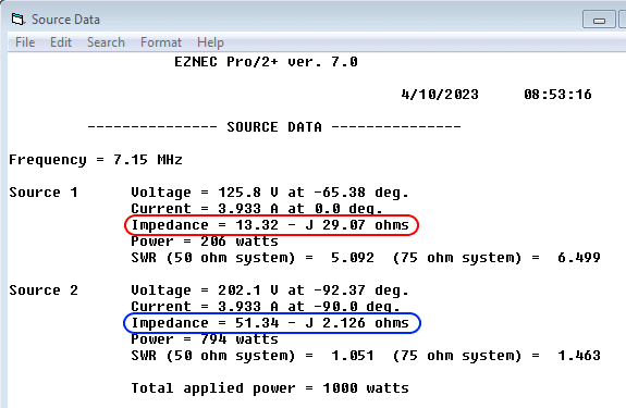
Click Src Dat, the drive impedances are shown for each element, these are fairly close to what Drive2EL calculated. After making inquiries, one of the authors of the phased array chapter in the ON4UN book noted the formulas in the spreadsheet included with the book are based on simple equations and models, where-as EZNEC/NEC2 calculation are based on complex models, they also noted that it's more important to get the currents correct in the array (by measuring them) than worry about small differences the impedances.
Open Feed2EL, set type to Simplest, enter the frequency 7.15, enter the drive impedances into Element 1 Z and I and Element 2 Z and I respectively, Phase -90.
Click Find Solution, the coax length values are calculated taking into account the type, impedance, and VF of the coax type used (Library), Belden 9258 RG-8X is selected.
If no solution is found, changing to 75 ohm coax will sometimes work. If not an L network (current forcing) should give a solution.
Note: To make the direction switchable in practice (per the Christman diagram at the top of the page), the shorter Line 1 length (94.36 degrees / 8.87 m) must reach each other at a common point from each element, the Line 1 length is then subtracted from the Line 2 length (185.15 degrees / 17.404 m), the difference (90.79 degrees 8.53 m ) is switched from one side to the other (adding back up to 185 degrees / 17.404 m) to reverse the direction of the array.
With the coax length values calculated, the EZNEC model can be updated to resemble the antenna system as it would be constructed in practice to see how it will perform over a given bandwidth.
V1 (virtual connection) becomes the junction where both lines meet and connect.
Delete source 2, change the remaining source to V1.
Add two transmission lines using the calculated values, the line from the first vertical (wire 1) and the line from the second vertical (wire 6 both connect to V1.
40m-2-GP-2-CDL.ez has the source updated and transmission lines added as above.
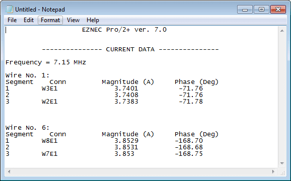
Click Currents and note the magnitudes on wire 1 and 6 (fairly close), and the phase (about 96 degrees), here I've just shown those two wires for convenience.
The currents shown are with the power level set to 1000 watts in EZNEC > Options > Power Level.
Click FF Plot, on the 3D view window click View > Show 2D Plot to see Elevation and Azimuth plots.
Check the pattern stability over a frequency range, here I've saved and added the traces for 7.05 and 7.25 MHz.
When I compared to using 2 x 84 and 71 degree lines, the F/B has dropped, and the Currents window showed the magnitudes are far from equal.
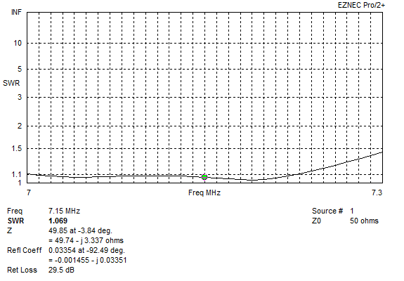
Click Src Dat, SWR is around 1.5:1, we can get that down using a series matching section of 75 ohm coax which Feed2EL will calculate.
Use series section calculator on the on the Feed2EL sheet to match to 50 ohms, add the transmission lines and virtual connections, update source virtual connection, Belden 9258 RG-8X 50 ohm, Belden 9116 RG-6 75 ohm coax is selected. Run SWR sweep.
40m-2-GP-3-CDL-Matched.ez has the matching sections added as above.
Overall this array looks good, the pattern and F/B degrades maybe more than we'd like at +/- 100 kHz, this is a limitation of using coax delay lines. However with the series matching also using coax, this array is phased and matched with coax keeping things simpler.
L Network (Current Forcing) with 20m Horizontal Dipoles
Current forcing is used in this example, this uses a pair of 1/4 wave lines and an L Network where they meet - this will work when a solution using coax delay lines (Christman) cant be found.
Note: With this array type Feed2EL does not find a solution with 50 or 75 ohm coax delay lines. 100 ohm, 37.5 or 25 ohm (e.g. 75 or 50 ohm coax ohm in parallel with the cores joined) will find a solution for coax lines, the series matching finds a solution with 25 ohm, so it would be possible to feed and match this array type using 50 ohm coax paralleled to make 25 ohm line.
This shows with some imagination a solution is possible, however I wanted to show an example using current forcing with commonly available coax.
Open the Drive2EL spreadsheet.
Open 20m-1-Dipole.ez, the dipole is 10 meters / 32.8 ft above average ground, and is resonant at 14.15 MHz.
Click Src Dat to see the source data self impedance, and enter these values into Drive2EL both Self Element 1 Z and Self Element 2 Z.
Note: When building an array in practice each antenna on its own may have a different self impedance, so each should be measured separately.
Add the 2nd element in the array using the copy wires command, offset X by 5.3, and uncheck Copy sources, loads, TL stubs.
Click Src Dat to see the source data coupled impedance, and copy the values into Coupled Element Z.
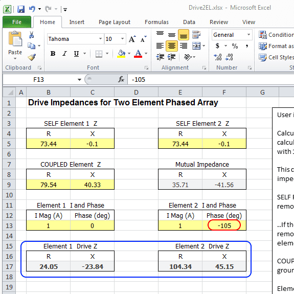
In Drive2EL Element 2 I and Phase change phase to -105, leave Element 1 I and Phase as 1 and 0.
The drive impedances for each element are now displayed.
EZNEC Drive Impedances
-----
Note: If simply experimenting with models we can skip to this step and use a two source model to see the drive impedances calculated directly by EZNEC.
The optimal phase for the array type and height can be found by experimenting with a two source model to find what seems good or suits a given goal and constraints, then plug the drive impedances into Feed2EL or Arrayfeed1 to calculate the coax lines or L network values.
When building the array the above process of taking measurements from the physical antenna elements should be done to confirm the model is accurate and/or to account for other factors in the environment that may affect the real world results.
-----
In EZNEC change add a second source to wire 2, and change the phase to -105, this amount of phase shift was found via some trial and error to see what gave the better end result for the given height above ground.
Click Src Dat, the drive impedances are shown for each element, these are fairly close to what Drive2EL calculated. After making inquiries, one of the authors of the phased array chapter in the ON4UN book noted the formulas in the spreadsheet included with the book are based on simple equations and models, where-as EZNEC/NEC2 calculation are based on complex models, they also noted that it's more important to get the currents correct in the array (by measuring them) than worry about small differences the impedances.
Open Feed2EL, set type to L Network, enter the frequency 14.15, enter the drive impedances into Element 1 Z and I and Element 2 Z and I respectively, Phase -105, Place Network On Line 2.
Click Find Solution, the L network values are calculated, and the 1/4 wave lines taking into account the type, impedance, and VF of the coax type used (Library), Belden 9116 RG-6 75 ohm coax is selected.
Delete source 2, change the remaining source to V1 (virtual connection).
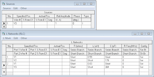
Add two transmission lines, one to each dipole, the line from dipole (wire) 1 connects to V1, and the line from dipole (wire) 2 to V2 using the calculated values.
Add an L network, and enter the calculated values for the series and shunt.
20m-2-Dipoles-1-CF.ez has the source updated, lines and L network added.
Click Currents and note the magnitudes the center segment 26 of each wire, and the phase, here I've just shown the 3 center segments of each wire for convenience.
The currents shown are with the power level set to 1000 watts in EZNEC > Options > Power Level.
Click FF Plot, on the 3D view window click View > Show 2D Plot to see Elevation and Azimuth plots.
Check the pattern stability over the frequency range, here I've saved and added the traces.
When I compared to using 2 x 84 and 71 degree lines, the F/B has mostly gone, and the Currents window showed the magnitudes are far from equal.
Click Src Dat, SWR not great. Use L network calculator on the on the Feed2EL sheet to match to 50 ohms, add L Network, update source virtual connection, run SWR sweep.
20m-2-Dipoles-2-CF-Matched.ez has the matching L network added.
Overall the array favors the lower end of the 20m band for pattern stability and SWR response when matched.
Some experimentation would be needed to optimize the pattern response across the band better depending on what we want, or how OCD we are :-)
I tried tuning the dipoles to resonance at the target frequency when coupled, as the coupling had lowered their resonance (coupled reading above showed a positive (+ J) reactance indicating that it is inductive or "too long" at 14.15 MHz). When I did this the elements were shortened to 10.115 meters, after re-calculating the phase shift L network the F/B held up better further up the band. After updating the matching L network values, the SWR sweep improved 1.17:1 at its highest.
Using models helps discover these characteristics which can then be accounted for when setting out to build the array for example.
ARRL Antenna Book covers current forcing in detail (Chapter 6 in 24th Edition).
G3WZT Phased Verticals - designed and built a 3 element vertical array using current forcing.
NA6O 40m Phased Vertical Array - 2 element elevated vertical array using current forcing.
There is also W7EL's Field Day Special which is two folded dipoles, phase fed, only matching network is a pair of series caps to tune out inductive reactance.
And the Moxon Rectangle, less width (ends are folded), direct 50 ohm feed (no matching network), no phasing system to adjust, less coax hanging up. That simply might be the best choice for a horizontal array? There are means to electrically reverse them (switched open/closed stubs).
Perhaps the current and voltage forcing (below) systems are better suited to vertical arrays ?
Other Feed Systems?
ON4UN's Low Band DXing book dives deep into detail on phased arrays and different feed systems.
Opposite Voltage Fed
One notable feed system that does not appear to be widely known is Opposite Voltage Fed (OVF) developed by OH1TV.
OVF uses 1/2 wavelength lines (voltage forcing), and a loading inductor or capacitor in series with one element. Since the lines are 1/2 wave the load can be placed at either end making for convenient direction switching.
From my modeling experiments with OVF it works with all element types (verticals, dipoles, loops, half squares), has a wider operational bandwidth, better pattern stability, and when matched a fairly good SWR response across the band.
More information about this system with examples can be found at:
- Phased Arrays - Opposite Voltage Fed (OVF) (links to a variety of array types by OH1TV).
- Phased Arrays - 40m 2 Element Horizontal.
- Phased Arrays - 40m Twin Half Square (impressive pattern and SWR response with OVF).
Acknowledgments
- AC6LA - Feed2EL (and other amazing tools).
- ON4UN's Low Band DXing - spreadsheet formulas used in Drive2EL.
- VK4NRO - Alerting me to the fact drive impedances can be calculated from the self and coupled impedances, which resulted in Drive2EL and a complete re-write of this page!
-----
Models are good starting point, and a way to investigate and better understand antenna systems. These tools can also help guide us to and validate the final result, if a good correlation is observed in the real world then we can have confidence the patterns and other information are accurate.
The models I have created and made available may contain errors, or overlook something someone more experienced can see. I don't claim to be an expert or authority on the subject of antenna modeling or phased arrays. I simply want to further my own knowledge and understanding of antennas which I find fascinating. Comments, suggestions, discussion are welcome - lonney@gmail.com.
This post is one of several on Phased Arrays.
